Mitsubishi CM150DC1-24NF IGBT Module: A Technical Review and Application Guide
Mitsubishi CM150DC1-24NF 1200V 150A IGBT Module
Introduction and Core Highlights
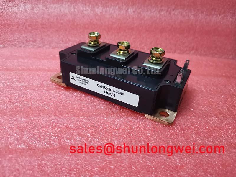
The Mitsubishi CM150DC1-24NF is an NF-Series dual IGBT module engineered for balanced performance in high-power switching applications. It provides a robust solution for systems requiring efficient power conversion and reliable operation, integrating two IGBTs in a standard industrial package. This design focuses on achieving low power loss and effective thermal management for demanding operational cycles.
- Core Specifications: 1200V | 150A | VCE(sat) (typ) 2.2V
- Key Advantages: Reduced conduction losses, high thermal efficiency via an isolated copper baseplate.
- This module is well-suited for power conversion systems where controlling heat dissipation is a primary design consideration.
Download Official Datasheet (PDF)

Technical Analysis for System Integration
A defining characteristic of the CM150DC1-24NF is its collector-emitter saturation voltage (VCE(sat)), with a typical value of 2.2V at its nominal current. This parameter is critical as it directly influences the module’s conduction losses—the primary source of heat generation during the on-state. A lower VCE(sat) means less power is dissipated as heat, which simplifies the requirements for the system’s cooling hardware. Think of the module’s thermal resistance as the width of a drain pipe for heat; the low junction-to-case thermal resistance (0.134°C/W for the IGBT part) signifies a wider pipe, allowing heat to be evacuated from the semiconductor junction more effectively.
The module’s construction features an electrically isolated baseplate, providing 2500V (RMS) of isolation. This simplifies mechanical assembly by allowing multiple modules to be mounted on a single heatsink without requiring separate insulating layers, a key consideration covered in guides to IGBT reliability. This integrated isolation reduces part count, mitigates potential assembly errors, and improves the overall thermal interface between the module and the heatsink.

Optimized Application Scenarios
The electrical and thermal characteristics of the CM150DC1-24NF make it a strong candidate for several medium-to-high power applications:
- General Purpose Inverters: The 1200V blocking voltage and 150A current rating provide ample headroom for industrial inverter designs, where robust performance is essential.
- AC and Servo Motor Controls: Fast and soft switching characteristics contribute to smoother motor operation and reduced electromagnetic interference (EMI), which is critical for precision control systems. A well-designed gate drive circuit is key to maximizing this performance.
- Uninterruptible Power Supplies (UPS): The module’s efficiency, characterized by its low VCE(sat), directly translates to lower operating costs and reduced cooling requirements in always-on UPS systems.
Its blend of voltage rating, current handling, and thermal efficiency makes the CM150DC1-24NF a versatile component for industrial power conversion.

Key Specifications of the CM150DC1-24NF
| Absolute Maximum Ratings | |
|---|---|
| Collector-Emitter Voltage (VCES) | 1200 V |
| Collector Current (IC) | 150 A |
| Peak Collector Current (ICM) | 300 A |
| Maximum Power Dissipation (Pc) | 930 W |
| Operating Junction Temperature (Tj) | -40 to +150 °C |
| Electrical & Thermal Characteristics | |
| Collector-Emitter Saturation Voltage (VCE(sat)) (Typ) | 2.2 V (at IC = 150A) |
| Gate-Emitter Threshold Voltage (VGE(th)) | 5.5 V to 7.5 V |
| Isolation Voltage (Visol) | 2500 Vrms (AC, 1 minute) |
| Thermal Resistance, Junction to Case (Rth(j-c)) (IGBT) | 0.134 °C/W |
Engineer’s FAQ
- What is the recommended mounting torque for the CM150DC1-24NF?
- The datasheet specifies a mounting torque for the main terminals (M5 screws) of 2.5 to 3.5 N·m and for the module mounting screws (M6) of 3.0 to 4.0 N·m. Applying incorrect torque can lead to poor thermal contact or mechanical stress.
- How does operating temperature affect VCE(sat)?
- VCE(sat) has a positive temperature coefficient. As the junction temperature increases from 25°C to 125°C, the VCE(sat) at 150A increases. This behavior is crucial for accurate loss calculations, a topic explored when mastering IGBT thermal design.
- What are the gate drive voltage requirements?
- The recommended gate drive voltage is +15V for turn-on and -15V for turn-off. The gate-emitter threshold voltage (VGE(th)) ranges from 5.5V to 7.5V, but driving it close to this threshold is not recommended for reliable switching.
- Is this module UL recognized?
- Yes, the datasheet indicates that the CM150DC1-24NF is a UL recognized component under file number E323585.
Enabling Efficient Power System Design
The CM150DC1-24NF provides a well-documented and robust foundation for power electronics. Its combination of a 1200V rating, 150A current capability, and favorable thermal characteristics offers engineers a reliable building block. The module’s design allows for the development of efficient, power-dense systems for a range of industrial applications.