Mitsubishi CM200DX-24A: A Technical Review for High-Power Applications
## Mitsubishi CM200DX-24A Dual IGBT Module: 1200V 200A
The Mitsubishi CM200DX-24A is a dual IGBT module that provides a robust and efficient solution for high-power switching systems. It is engineered to balance low conduction losses with controlled switching performance, making it a reliable component for demanding industrial inverter applications. With core specifications of 1200V and 200A, this module’s electrical and thermal characteristics are well-defined, allowing for precise and predictable system design. Key engineering benefits include a standard package that simplifies thermal management and a half-bridge configuration that streamlines the layout of three-phase power stages.
* **Core Specifications:** 1200V | 200A | VCE(sat) 2.7V (max)
* **Key Advantages:** Low conduction losses, simplified thermal design, and high operational reliability.
* **Design Focus:** The module’s detailed thermal resistance data enables accurate calculation of heatsink requirements, ensuring stable long-term operation.
Download the Official CM200DX-24A Datasheet (PDF)

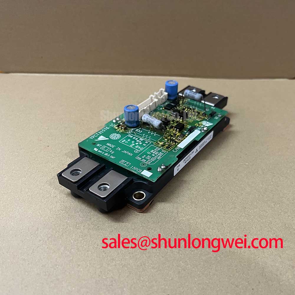

### Technical Analysis for System Integration
A successful power electronics design hinges on managing the trade-off between conduction and switching losses. The **CM200DXDX1-24A+YPCT31576-1C** datasheet provides the necessary data to navigate this balance. The collector-emitter saturation voltage (VCE(sat)) is specified at a maximum of 2.7V at 200A and a junction temperature of 125°C, a key parameter for calculating on-state power dissipation. This value directly impacts the thermal load on the module, and a lower value translates to higher efficiency.
Thermal management is critical for reliability. The module’s thermal resistance, Rth(j-c), can be thought of as the width of a pipe for heat transfer; a lower value allows heat to escape the semiconductor junction more easily. For the CM200DX-24A, the IGBT has a junction-to-case thermal resistance of 0.085°C/W, and the free-wheeling diode (FWD) is rated at 0.16°C/W. These figures are essential for engineers to accurately model thermal performance and select an appropriate heatsink to maintain the junction temperature below the 150°C maximum rating, which is vital for achieving a long operational life. For further reading, an engineer can explore how to use the Zth curve for thermal design.
The module’s robustness is further defined by its short-circuit withstand time (tsc) of 10µs, which provides a critical safety margin against catastrophic failure during fault conditions common in motor drive applications. The half-bridge, or dual, configuration simplifies the construction of three-phase inverters, as three modules can form a complete power stage. The inclusion of a discrete super-fast recovery free-wheel diode is essential for handling the reactive currents from inductive loads like electric motors.


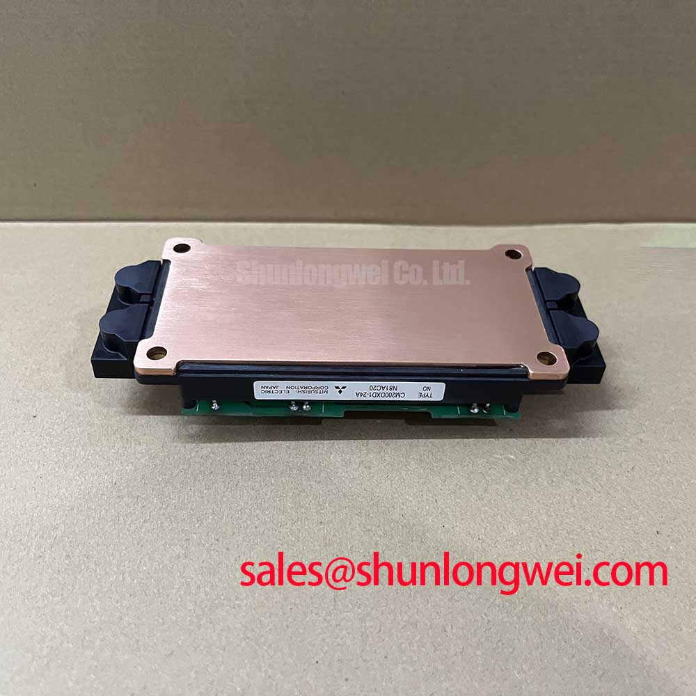
### Optimized Application Scenarios
The electrical and thermal specifications of the CM200DX-24A make it well-suited for several high-power industrial applications.
* **AC Motor Control & VFDs:** The 1200V rating provides a robust safety margin for inverters operating on 400V to 480V AC lines. Its 200A capacity is ideal for controlling medium-power industrial motors, where torque and speed control are paramount.
* **Motion/Servo Control:** The module’s defined switching characteristics allow for precise control loops necessary in high-performance servo drives, ensuring accurate positioning and motion profiles.
* **Uninterruptible Power Supplies (UPS):** The balance between low VCE(sat) and switching energy ensures high efficiency, reducing operating costs and cooling requirements in critical power backup systems.
* **Welding Equipment:** The module’s ability to handle high peak currents (ICM up to 400A) and its short-circuit robustness are critical for the demanding, pulsed-power nature of welding applications.
This module is an optimal match for three-phase inverters, delivering reliable performance based on its well-defined and predictable thermal and electrical characteristics.
### Key Specifications of the CM200DX-24A
| Absolute Maximum Ratings (Tj = 25°C) | ||
|---|---|---|
| Collector-Emitter Voltage (VCES) | 1200V | |
| Collector Current (IC) @ TC=90°C | 200A | |
| Peak Collector Current (ICM) | 400A | |
| Maximum Power Dissipation (PC) | 1470W | |
| Gate-Emitter Voltage (VGES) | ±20V | |
| Isolation Voltage (Visol) | 2500V (AC, 1 minute) | |
| Electrical & Thermal Characteristics (Tj = 125°C unless noted) | ||
| Collector-Emitter Saturation Voltage (VCE(sat)) @ 200A | 2.2V (typ), 2.7V (max @ 25°C) | |
| Gate-Emitter Threshold Voltage (VGE(th)) | 7.0V (typ) | |
| FWD Emitter-Collector Voltage (VEC) @ 200A | 2.16V (typ) | |
| Thermal Resistance, Junction-to-Case (Rth(j-c)) – IGBT | 0.085°C/W (max) | |
| Thermal Resistance, Junction-to-Case (Rth(j-c)) – Diode | 0.16°C/W (max) | |
Note: All specifications are based on the official CM200DX-24A datasheet. For complete and up-to-date information, refer to the manufacturer’s documentation.
### Engineer’s FAQ
**1. How do I determine the right heat sink for the CM200DX-24A?**
To select a heatsink, you must calculate the total thermal resistance from junction to ambient. Start with the module’s maximum junction-to-case thermal resistance (Rth(j-c)), which is 0.085°C/W per IGBT. Add the thermal resistance of your thermal interface material (Rth(c-s)) and the heatsink-to-ambient resistance (Rth(s-a)). The total power loss multiplied by this total resistance must keep the junction temperature below its 150°C maximum.
**2. What are the recommended gate driver voltage levels?**
The datasheet specifies a gate-emitter threshold voltage (VGE(th)) between 6V and 8V. For reliable switching, a standard gate drive voltage of +15V for turn-on and -15V for turn-off is recommended. Using a negative voltage for turn-off helps prevent parasitic turn-on events caused by high dv/dt, an important consideration in bridge topologies. You can learn more by reading this guide to robust gate drive design.
**3. Is the CM200DXDX1-24A+YPCT31576-1C suitable for paralleling?**
Yes, paralleling is feasible. The VCE(sat) exhibits a positive temperature coefficient, which helps to naturally balance current between parallel modules. However, achieving effective current sharing requires a highly symmetrical PCB and busbar layout to minimize differences in stray inductance. For guidance on this, see the principles of high-power IGBT paralleling.
**4. What is the role of the integrated NTC thermistor?**
The module includes an NTC (Negative Temperature Coefficient) thermistor. Its purpose is to provide a real-time temperature feedback signal from the module’s baseplate to the system controller. This allows for over-temperature protection, ensuring the module operates within its safe thermal limits and enhancing overall system reliability.
### Enabling Reliable Power Conversion
By providing a well-documented balance of electrical performance, thermal stability, and a proven industrial package, the CM200DX-24A enables engineers to develop efficient and reliable high-power conversion systems. Its straightforward design and robust ratings offer a dependable foundation for motor drives, power supplies, and other demanding switching applications.