Mitsubishi CM30E3Y-24 IGBT Module: A Technical Review and Application Guide
Mitsubishi CM30E3Y-24 1200V 30A IGBT Module
Reliable High-Power Switching with Balanced Performance
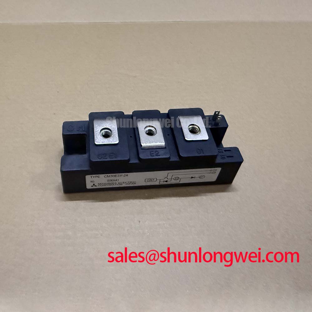
The Mitsubishi CM30E3Y-24 is an N-channel IGBT module engineered for reliability in demanding high-power switching applications. It provides a robust balance between conduction and switching efficiency. This makes it a versatile component for various power conversion systems. Its specified junction-to-case thermal resistance provides the necessary data for accurate heatsink selection and thermal modeling, a key aspect of system longevity.
- Core Specifications: 1200V | 30A | VCE(sat) 2.7V (max)
- Key Advantages: Facilitates straightforward thermal management, enables reliable operation in industrial inverters.
Download Official Datasheet (PDF)

Technical Analysis for System Integration
The performance of the CM30E3Y-24 is defined by a carefully balanced set of parameters. The maximum collector-emitter saturation voltage (VCE(sat)) is specified at 2.7V (with Ic=30A, Tj=25°C), which dictates the power lost as heat during the on-state. This parameter is critical for calculating conduction losses and informs the thermal design of the entire system. Lower conduction losses translate directly to reduced cooling requirements and improved overall energy efficiency. Understanding this value is a crucial first step in mastering IGBT thermal design.
Controlled switching dynamics are equally important for system reliability. With a maximum turn-on time (ton) of 0.35µs and turn-off time (toff) of 0.70µs, the module is optimized for industrial applications operating at moderate switching frequencies. These characteristics help to minimize switching losses without introducing excessive electromagnetic interference (EMI), simplifying the design of the gate drive circuitry. The module’s thermal resistance from junction to case (Rth(j-c)) is analogous to the diameter of a pipe draining heat from the active silicon. The specified maximum value of 0.83°C/W signifies an efficient thermal pathway, ensuring that heat is effectively transferred to the heatsink.

Optimized Application Scenarios
The electrical and thermal characteristics of the CM30E3Y-24 make it highly suitable for a range of industrial power systems.
- Variable Frequency Drives (VFDs): The 1200V rating offers a substantial safety margin for inverters operating on 400V or 480V AC lines, making it ideal for controlling small to medium-sized induction motors.
- Uninterruptible Power Supplies (UPS): Its reliable switching performance and robust voltage blocking capability are essential for the inverter stage, ensuring stable AC output during power disruptions.
- Welding Power Supplies: The module’s ability to handle pulsed currents and its efficient thermal dissipation are well-suited for the demanding, cyclical loads found in modern welding equipment.
- General-Purpose Inverters: The balanced performance profile supports various AC power conversion tasks where efficiency and reliability are primary objectives.
This module is an optimal match for industrial systems requiring dependable 1200V switching at currents up to 30A with a straightforward thermal design.
Key Specifications of the CM30E3Y-24
| Electrical and Thermal Characteristics (Tj = 25°C unless otherwise noted) | ||
|---|---|---|
| Parameter | Symbol | Value (Max) |
| Absolute Maximum Ratings | ||
| Collector-Emitter Voltage | VCES | 1200 V |
| Gate-Emitter Voltage | VGES | ±20 V |
| Collector Current (DC) | IC | 30 A |
| Collector Power Dissipation (Tc=25°C) | Pc | 150 W |
| Electrical Characteristics | ||
| Collector-Emitter Saturation Voltage (IC=30A) | VCE(sat) | 2.7 V |
| Gate-Emitter Threshold Voltage (IC=3mA) | VGE(th) | 8.0 V |
| Thermal & Isolation Characteristics | ||
| Thermal Resistance (Junction to Case, IGBT) | Rth(j-c) | 0.83 °C/W |
| Isolation Voltage (Terminals to Baseplate, AC 1 min) | Viso | 2500 Vrms |


Engineer’s Frequently Asked Questions
1. How do I use the datasheet’s thermal resistance (Rth) value to select a heatsink for the CM30E3Y-24?
The junction-to-case thermal resistance, Rth(j-c), is 0.83°C/W. To select a heatsink, first calculate the total power dissipation (P_total) from conduction and switching losses. Then, determine the maximum allowable case temperature based on your maximum operating junction temperature (e.g., 125°C) and P_total. The required heatsink thermal resistance (Rth(c-a)) can be estimated using the formula: Rth(c-a) = (Tj_max – Ta_max) / P_total – Rth(j-c). Always add a safety margin.
2. What are the recommended mounting torque specifications for this module?
According to the official datasheet, the recommended mounting torque for the main terminals (M5 screws) is 2.5 to 3.5 N·m. For mounting the module to a heatsink (M5 screws), the recommended torque is also 2.5 to 3.5 N·m. Adhering to these values ensures proper electrical and thermal contact without causing mechanical stress.
3. Is a freewheeling diode (FWD) included in the CM30E3Y-24?
No, the CM30E3Y-24 is a single IGBT module. It does not contain an integrated, co-packaged freewheeling diode. For bridge or chopper circuit topologies, an external fast-recovery diode with appropriate voltage and current ratings must be used. For more information, see our guide on the role of the free-wheeling diode.
4. What is the typical gate-emitter threshold voltage (VGE(th))?
The datasheet specifies the VGE(th) to be between 4.0V and 8.0V. This is the minimum gate-emitter voltage required to begin turning the IGBT on. A gate drive voltage significantly higher than this range (typically +15V) is required to fully saturate the device and achieve the low VCE(sat) specified.
Enabling Robust Power Conversion
The CM30E3Y-24 offers a well-documented and reliable foundation for power electronics design. Its balanced approach to voltage rating, current handling, and thermal performance allows engineers to develop efficient and durable power conversion systems with predictable behavior. This module is a practical choice for achieving cost-effective and robust industrial-grade power stages.