Powerex PM150RL1A060 IPM: A Comprehensive Technical Review
Powerex PM150RL1A060 Intellimod™ L1-Series IPM Technical Review
Introduction and Core Highlights
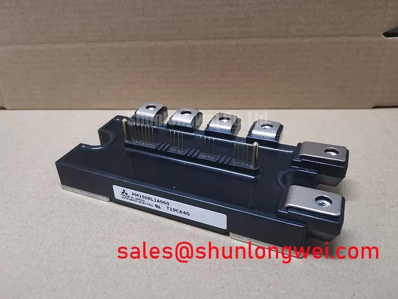
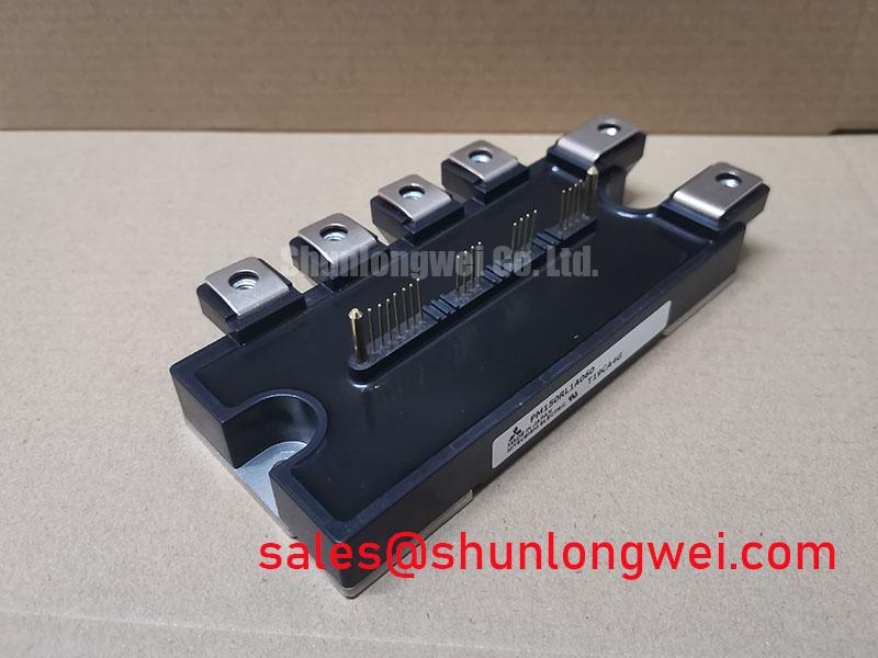
The Powerex PM150RL1A060 is a highly integrated Intellimod™ L1-Series Intelligent Power Module (IPM) that delivers a robust solution for three-phase inverter systems. This module consolidates a three-phase IGBT inverter stage, a brake chopper, dedicated gate drivers, and comprehensive protection circuits into a single compact package. Its core value proposition is the simplification of power stage design and a significant enhancement in system reliability through built-in protection mechanisms. By integrating these elements, engineers can accelerate development time and reduce PCB complexity.
- Core Specifications: 600V | 150A | Integrated 7-Pack with Brake Circuit
- Key Advantages: Provides integrated short-circuit, over-temperature, and under-voltage protection. The inclusion of an NTC thermistor facilitates precise thermal management.
Download the Official PM150RL1A060 Datasheet (PDF)

Technical Analysis of Integrated Features
The defining characteristic of the PM150RL1A060 is its high level of integration, which provides significant engineering advantages. By packaging the IGBTs, freewheeling diodes, and optimized gate drivers together, the module minimizes stray inductance between the driver and the IGBT gates. This is a critical factor in reducing voltage overshoots during high-speed switching events, which enhances the overall robustness of the power stage. This integrated approach, a hallmark of Intelligent Power Modules (IPM), abstracts away the complexity of gate drive design and component matching.
Advanced, Built-in Protection for System Reliability
A key value of this IPM is its comprehensive suite of protection features. The module provides on-board protection against short-circuits (SC), control supply under-voltage (UV), and over-temperature (OT). The OT protection is particularly noteworthy; it utilizes an integrated NTC thermistor to directly monitor the module’s substrate temperature. Think of this NTC thermistor as a built-in, real-time thermometer for the module’s core. Unlike external sensors that can have a delay in detecting temperature rises, this internal sensor provides immediate feedback, allowing the control system to trigger a fault signal and initiate a shutdown before the junction temperature exceeds its maximum rating of 150°C. This proactive protection is crucial for preventing catastrophic failures in the field.
Thermal Performance and Heatsink Design
Efficiently managing heat is essential for reliability. The PM150RL1A060 datasheet specifies the thermal resistance from junction to case (Rth(j-c)Q) for the IGBT as 0.25°C/W (max). This parameter can be visualized as the width of a pipe; a lower thermal resistance value signifies a wider pipe, allowing heat to flow more easily from the active silicon chip to the heatsink. This value is a fundamental input for calculating the required heatsink performance to keep the IGBT junction temperature within the Safe Operating Area (SOA) under expected load conditions, ensuring long-term operational stability.
Optimized Application Scenarios
The features of the PM150RL1A060 make it a strong candidate for several power conversion applications:
- General Purpose Inverters & VFDs: The module’s all-in-one design, including a brake circuit and robust protection, is ideal for the dynamic loads found in motor control, reducing system size and component count.
- Servo Drives: High integration and built-in protection contribute to the compact form factor and high reliability required for precision motion control systems.
- Uninterruptible Power Supplies (UPS): The integrated under-voltage and short-circuit protection ensures the inverter stage is protected against grid and load faults, a critical requirement for high-availability systems.
With its 150A current rating and comprehensive protection, this module is an excellent match for three-phase motor drives and inverters up to approximately 55kW.
Key Specifications of the PM150RL1A060
| Key Parameters | ||
|---|---|---|
| Parameter | Value | Notes |
| Absolute Maximum Ratings (Tj = 25°C) | ||
| Collector-Emitter Voltage (Vces) | 600 V | Inverter & Brake Part |
| Collector Current (Ic) | 150 A | TC = 25°C |
| Peak Collector Current (Icp) | 300 A | t = 1ms |
| Collector Dissipation (Pc) | 500 W | Per IGBT |
| Isolation Voltage (Viso) | 2500 Vrms | AC 1 minute |
| Electrical & Thermal Characteristics (Tj = 25°C) | ||
| Collector-Emitter Saturation Voltage (VCE(sat)) | 2.2V (Typ), 2.7V (Max) | At Ic = 150A |
| Short Circuit Withstand Time (tsc) | > 10 µs | Vcc=15V, Vces < 400V |
| Thermal Resistance (Rth(j-c)Q) | 0.25 °C/W (Max) | IGBT Part, Per 1 Element |
Engineer’s FAQ
- How does the integrated short-circuit (SC) protection in the PM150RL1A060 work?
- The IPM uses a current-sensing function on the IGBT emitters. If the collector current exceeds a predefined threshold, the internal control logic recognizes a short-circuit event. It then safely shuts down the IGBTs in that arm and sends a fault signal (Fo) to the system microcontroller. This built-in function acts much faster than external monitoring circuits, preventing destructive IGBT failures.
- What are the key considerations for thermal design with this IPM?
- The primary goal is to ensure the junction temperature (Tj) remains below the 150°C maximum rating. Start by calculating total power loss (conduction and switching). Use the specified maximum thermal resistance, Rth(j-c) of 0.25 °C/W for the IGBT, to determine the maximum allowable case temperature. Then, select a heatsink with an appropriate Rth(c-f) and Rth(f-a) to maintain the case temperature below this limit under worst-case ambient conditions. The integrated NTC thermistor should be used for real-time monitoring.
- What are the recommended supply voltages for the control section?
- The datasheet specifies a single 15V DC supply for the control circuits (VUP1, VVP1, VWP1, VN1). These supply pins should be operated within a range of 13.5V to 16.5V. The under-voltage protection will trigger if this supply drops below approximately 11.9V.
- The datasheet specifies a max VCE(sat) of 2.7V. What is the impact of this?
- VCE(sat) is the on-state voltage drop across the IGBT at its rated current. This value is a direct contributor to conduction losses (Power Loss = VCE(sat) * Ic). A VCE(sat) of 2.7V at 150A means that under full load, each IGBT will generate approximately 405 watts of heat due to conduction. This figure is critical for accurate thermal modeling and heatsink selection.
Enabling Reliable Power Conversion
The PM150RL1A060 gives engineers a validated power stage with integrated intelligence. By handling the complexities of gate drive, level-shifting, and critical fault protection internally, this module allows design teams to focus on system-level control and application-specific logic. The result is a more compact, reliable, and faster-to-market power conversion system for demanding industrial applications.