Shindengen S20VTA60: A 600V Three-Phase Diode for Simplified Thermal Management
Shindengen S20VTA60 600V 20A Three Phase Bridge Diode
High-Reliability AC Rectification with Simplified Thermal Management
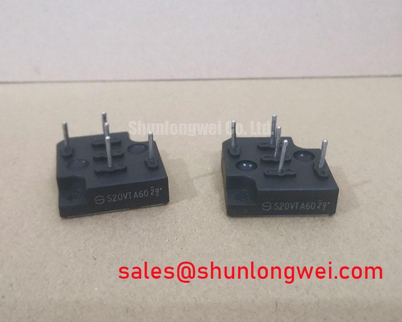
The Shindengen S20VTA60 is a three-phase bridge diode module engineered for robust performance in industrial power conversion systems. Its defining feature is a fully isolated mounting base, which streamlines thermal design and enhances system reliability by simplifying assembly. This module integrates six diodes in a three-phase bridge configuration within a compact, transfer-molded VTA package, providing a dependable solution for AC-to-DC rectification.
- Core Specifications: 600V VRRM | 20A IF(AV) | 2.5kV Visol
- Key Advantages: Eliminates need for external insulation, enabling direct heatsink mounting. High surge current capability enhances durability.
This design directly addresses the common engineering challenge of ensuring both electrical isolation and effective heat dissipation, reducing component count and assembly complexity.
Download the Official S20VTA60 Datasheet (PDF)

Technical Analysis for System Integration
The primary value of the S20VTA60 lies in its construction. The VTA package features an isolation voltage (Visol) of 2500V between the terminals and the mounting base. This high level of isolation allows engineers to mount the module directly onto a chassis or heatsink without needing additional insulating materials like mica pads or thermal grease. This not only simplifies the manufacturing process but also improves the consistency of thermal performance by creating a direct, unimpeded path for heat transfer.
The thermal efficiency of this module is quantified by its low thermal resistance from junction to case (Rth(j-c)) of 1.2°C/W. Think of thermal resistance as the narrowness of a pipe through which heat must flow; a lower value signifies a wider pipe. This efficient heat extraction capability is critical for maintaining a low operating junction temperature (Tj), which is directly linked to the component’s long-term reliability and operational lifespan, a concept explored further in guides to mastering IGBT thermal design. The module’s robust design is further proven by its high non-repetitive surge forward current (IFSM) rating of 250A (50Hz), ensuring survival during line disturbances or inrush current events.
Optimized Application Scenarios
The specific characteristics of the S20VTA60 make it a strong candidate for several demanding industrial applications:
- Variable Frequency Drives (VFDs): Its 600V blocking voltage is well-suited for the front-end rectifier in 200/400V class motor drives. The isolated baseplate is a major advantage in compact, power-dense VFD enclosures.
- Industrial Power Supplies: The 20A average forward current and high surge rating provide the necessary robustness for rectifying the main AC input for industrial-grade SMPS.
- Servo Motor Controllers: Provides reliable DC bus voltage for precision motion control systems, where simplified assembly and dependable thermal performance are key.
- Battery Charging Systems: Efficiently converts AC power for DC charging applications, where its durability ensures consistent operation.
This rectifier is best matched for industrial systems requiring robust AC-to-DC conversion with simplified assembly and reliable thermal management.
Key Specifications of the S20VTA60
| Absolute Maximum Ratings (Tc=25°C) | |
|---|---|
| Repetitive Peak Reverse Voltage (VRRM) | 600 V |
| Average Rectified Forward Current (IF(AV)) | 20 A |
| Surge Forward Current (IFSM) | 250 A (50Hz, 1 cycle) |
| Junction Temperature (Tj) | -40 to +150 °C |
| Electrical & Thermal Characteristics | |
| Forward Voltage (VF) @ 10A | 1.05 V (Max) |
| Repetitive Peak Reverse Current (IRRM) @ VRRM | 10 µA (Max) |
| Isolation Voltage (Visol) | 2.5 kV (Terminals to Mounting Base) |
| Thermal Resistance (Rth(j-c)) | 1.2 °C/W (Junction to Case) |
Engineer’s FAQ for the S20VTA60
What is the primary benefit of the S20VTA60’s isolated mounting base?
The key benefit is simplified thermal design. Its 2.5kV isolation rating allows direct mounting to a heatsink or system chassis without requiring a separate, fragile insulating layer. This reduces assembly time, lowers component count, and creates a more reliable thermal interface.
How do I calculate the required heatsink for this device?
To determine the required heatsink, you must first calculate the total power dissipation (PD) of the module under your operating conditions. Then, use the maximum allowable junction temperature (e.g., 125°C for a design margin) and the ambient temperature (TA) in the formula: Rth(c-a) = (Tj(max) – TA) / PD – Rth(j-c). The result, Rth(c-a), is the maximum thermal resistance your heatsink-to-ambient path can have.
Can the S20VTA60 be used for a single-phase application?
Yes. While designed as a three-phase bridge, you can use it for single-phase rectification by connecting the AC input to two of the AC terminals (e.g., R and S) and leaving the third unused. The DC output remains on the positive (+) and negative (-) terminals.
What is the maximum forward voltage drop (VF) specified in the datasheet?
The datasheet specifies a maximum forward voltage drop of 1.05V per diode when conducting a forward current of 10A at a junction temperature of 25°C.
Enabling Reliable Power Conversion
The S20VTA60 three-phase bridge diode provides a foundational component for modern power semiconductors and systems. By integrating high electrical isolation with effective thermal characteristics into a single, compact package, it allows engineers to develop more robust, compact, and cost-effective power conversion stages for a wide range of industrial equipment.