Technical Analysis of the Mitsubishi QM75DY-H 600V 75A IGBT Module
Mitsubishi QM75DY-H Dual IGBT Module | 600V 75A
Introduction and Core Highlights
The Mitsubishi QM75DY-H is a dual IGBT module engineered for reliable power switching in demanding industrial applications. This module’s primary value lies in its balanced performance and robust, electrically isolated package, which simplifies thermal design and system assembly. By integrating two IGBTs in a half-bridge configuration, it provides a fundamental building block for compact and efficient power inverters. How much power can the QM75DY-H handle? With a collector power dissipation rating of 350 watts, it is well-suited for medium-power motor control and power supply systems.
- Core Specifications: 600V | 75A | 2500V Isolation
- Key Advantages: Simplified thermal management with an isolated baseplate, and a proven design for high-reliability industrial systems.
Download the QM75DY-H Datasheet (PDF)
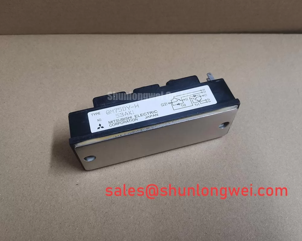
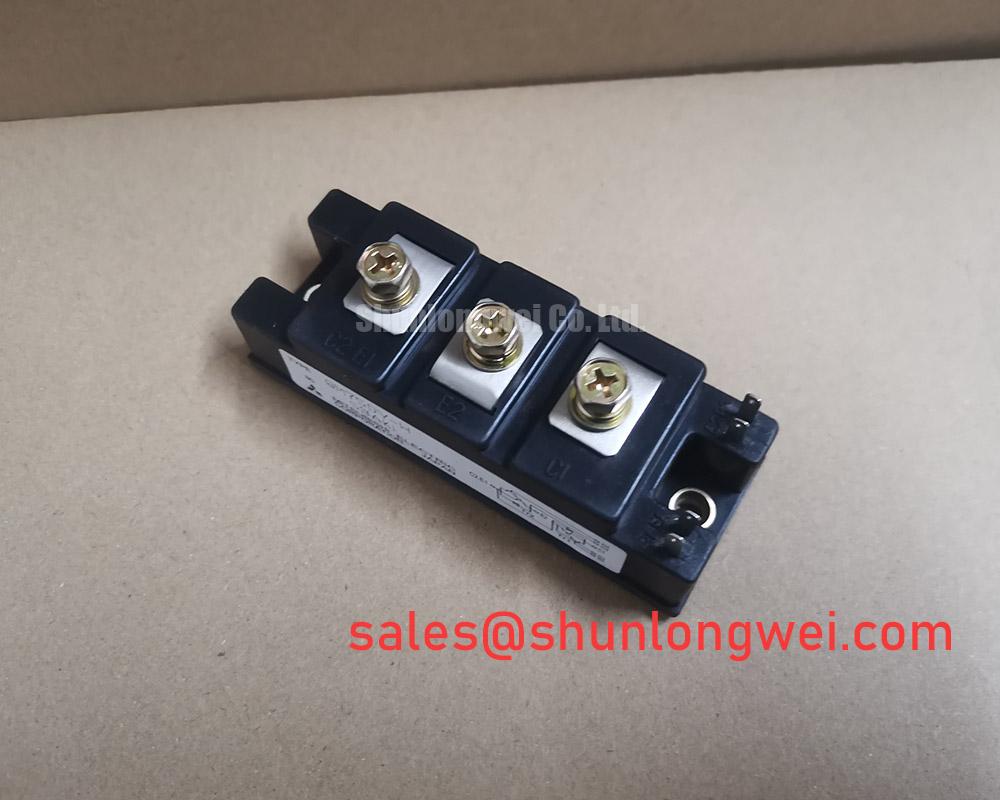
Technical Analysis for System Integration
The engineering value of the QM75DY-H is rooted in its practical design features that streamline manufacturing and ensure reliable operation. A key feature is its electrically isolated baseplate, which provides a Visol rating of 2500V (AC for one minute). This allows the module to be mounted directly onto a grounded heatsink without requiring a separate, fragile insulating layer. This not only reduces component count and assembly complexity but also enhances thermal transfer and minimizes the risk of insulation breakdown over the product’s lifetime.
The module’s performance characteristics demonstrate a well-engineered balance between on-state losses and switching speed. With a maximum collector-emitter saturation voltage (VCE(sat)) of 2.7V at its rated 75A current, conduction losses are kept within a manageable range for medium-power applications. This is complemented by typical switching times (turn-on, turn-off) of 0.3 microseconds. This balance makes the QM75DY-H a suitable component for systems operating at common PWM frequencies, such as those found in Variable Frequency Drives (VFDs).
Efficient heat dissipation is critical for reliability, and this is where thermal resistance becomes a key parameter. The junction-to-case thermal resistance (Rth(j-c)) for the IGBT is specified at 0.36°C/W. You can think of thermal resistance as the narrowness of a pipe for heat flow; a lower value means heat can escape more easily. This low thermal resistance ensures that heat generated within the silicon can be efficiently transferred to the module’s case, a crucial first step in effective thermal management.

Optimized Application Scenarios
The QM75DY-H’s specifications make it a strong candidate for several industrial power conversion applications:
- AC Motor Control: The dual IGBT configuration is ideal for constructing one phase leg of a three-phase inverter, making it a core component for AC motor drives.
- Uninterruptible Power Supplies (UPS): Its 75A rating and proven reliability are essential for building robust inverters and converters in UPS systems.
- Welding Power Supplies: The module’s ability to handle high currents makes it suitable for the power stages of industrial welding equipment.
- Servo Drives: Fast and precise control in servo applications is supported by the module’s consistent switching characteristics.
This module is best matched for medium-frequency power systems where a balance of performance, reliability, and simplified thermal design is the primary objective.
Key Specifications of the QM75DY-H
| Electrical and Thermal Characteristics (Tj=25°C) | ||
|---|---|---|
| Parameter | Symbol | Value |
| Collector-Emitter Voltage | VCEX | 600 V |
| Collector Current (DC) | IC | 75 A |
| Collector-Emitter Saturation Voltage (Max) | VCE(sat) | 2.7 V (at IC = 75A) |
| Collector Power Dissipation | PC | 350 W |
| Isolation Voltage (AC, 1 min.) | Viso | 2500 V |
| Thermal Resistance (Junction to Case, IGBT) | Rth(j-c)Q | 0.36 °C/W |
| Operating Junction Temperature | Tj | -40 to +150 °C |
Note: These values are summaries. For complete specifications and operating conditions, refer to the official datasheet.
Engineer’s FAQ
- What is the recommended heatsink thermal resistance for the QM75DY-H?
- To determine the required heatsink thermal resistance, you must first calculate the total power dissipation in your application. Using the formula Tj = Ta + P_diss * (Rth(j-c) + Rth(c-f) + Rth(f-a)), you can solve for the heatsink-to-ambient resistance (Rth(f-a)). The datasheet provides the junction-to-case (Rth(j-c)) value of 0.36°C/W and a case-to-fin (Rth(c-f)) value of 0.09°C/W (with thermal compound). A proper calculation is essential for reliable operation.
- What is the correct mounting torque for this module?
- According to the datasheet, the recommended mounting torque for the main terminal screws (M5) is 1.47 to 1.96 N·m. For the module mounting screws (M6), the recommended torque is 1.96 to 2.94 N·m. Adhering to these specifications is critical to ensure proper thermal contact and avoid mechanical stress.
- How can this dual module be used in a three-phase inverter?
- Three QM75DY-H modules are required to build a standard three-phase inverter. Each dual module serves as one of the three phase legs (a half-bridge), connecting to one of the motor phases. This modular approach is common in industrial power semiconductor systems.
Enabling Robust Power System Design
The QM75DY-H offers a dependable and cost-effective solution for power conversion systems. Its standard industrial package and integrated isolation simplify the design and assembly process, allowing engineers to focus on system-level optimization. The module’s balanced electrical and thermal characteristics provide a solid foundation for building reliable motor drives, power supplies, and other medium-power industrial equipment.