VS-85HFR40: 85A 400V Standard Recovery Stud Mount Diode for Industrial Rectification
VS-85HFR40 Vishay Standard Recovery Diode 85A 400V Stud Mount
Rugged Industrial Rectification and Core Highlights
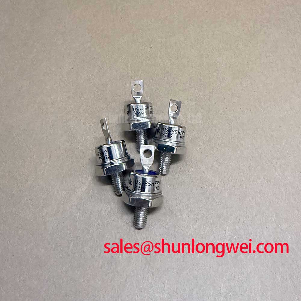
The VS-85HFR40 is a high-performance standard recovery diode engineered for heavy-duty industrial rectification. This stud-version power diode combines exceptional surge resilience with a wide operating temperature range. Its unique value proposition (UVP) lies in its rugged stud-mount design, which offers superior vibration resistance and simplified thermal integration compared to standard plastic discretes. Within the broader category of power semiconductors, the VS-85HFR40 remains a reliable choice for high-current applications that demand long-term mechanical and electrical stability.
- Core Specifications: 400V VRRM | 85A IF(AV) | 1.2V VF (at 267A pk)
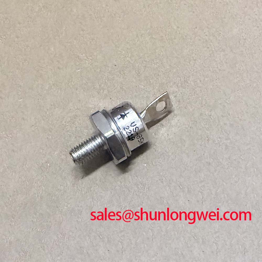
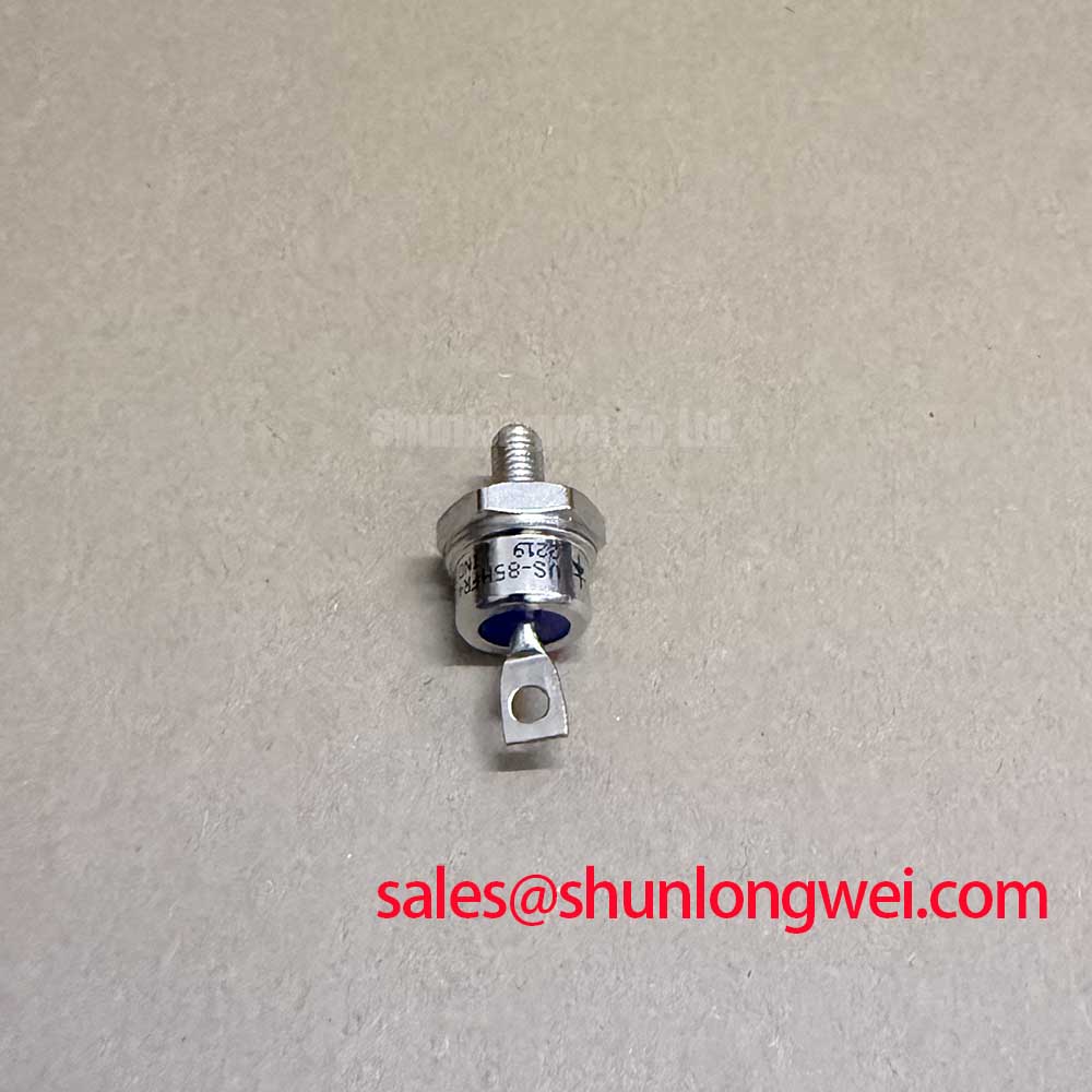
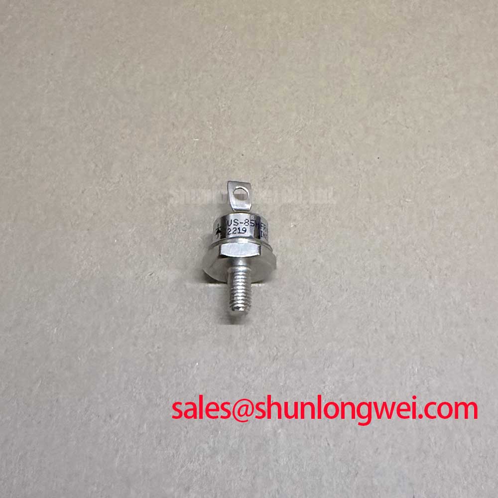
- Mechanical Integrity: The stud-mount DO-203AB (DO-5) metal case ensures robust heat dissipation and mechanical security in high-vibration environments.
- Thermal Range: Operates reliably with a maximum junction temperature of 180°C, significantly reducing the complexity of cooling systems in compact enclosures.
Download Official VS-85HFR40 Datasheet (PDF)

Technical Analysis of Performance Parameters
The engineering value of the VS-85HFR40 is anchored in its massive surge current capability. With a maximum non-repetitive peak forward current ($I_{FSM}$) of 1450A at 50Hz, this device is built to survive transient overloads that would destroy smaller components. You can visualize the surge capability as a structural dam; while the average current rating describes the daily flow, the $I_{FSM}$ defines the maximum flood level the device can withstand without catastrophic structural failure.
Thermal management for this stud diode is defined by its low junction-to-case thermal resistance ($R_{thJC}$) of 0.35 K/W. This parameter acts like the width of a thermal highway, where a lower value allows heat to flow away from the silicon more efficiently toward the heatsink. Achieving this performance requires strictly following the specified terminal torque management standards. Excessive torque can deform the metal base, while insufficient torque increases contact resistance, both leading to premature thermal aging.
Optimized Application Scenarios
The VS-85HFR40 is specifically suited for hardware where passive cooling and mechanical ruggedness are prioritized. Its electrical characteristics make it ideal for the following applications:
- Industrial Battery Chargers: The high $I^2t$ rating (10500 $A^2s$) allows for robust handling of high-energy pulses during initial charging phases.
- Welding Power Supplies: Resilience against high duty cycles and the thermal cycling typical of industrial welding equipment.
- Machine Tool Controls: The stud-mount design thrives in environments where constant vibration would otherwise fatigue traditional PCB-mounted components.
- General Purpose Rectification: Effectively handles mains-frequency rectification for large DC motors and power distribution systems.
Best Match Conclusion: The VS-85HFR40 is most effective in high-vibration power systems requiring decentralized thermal dissipation and high surge resilience.
Key Technical Specifications
| Parameter Group | Value |
|---|---|
| Maximum Average Forward Current ($I_{F(AV)}$) | 85 A @ $T_C$ = 110 °C |
| Peak Repetitive Reverse Voltage ($V_{RRM}$) | 400 V |
| Max. Peak One-Cycle Non-Repetitive Surge Current ($I_{FSM}$) | 1450 A (50 Hz) |
| Maximum $I^2t$ for Fusing (50 Hz) | 10500 $A^2s$ |
| Thermal Resistance, Junction to Case ($R_{thJC}$) | 0.35 K/W |
| Mounting Torque Range | 2.3 to 3.4 N·m |
Engineer’s FAQ: VS-85HFR40 Practical Implementation
Q1: What is the difference between VS-85HF and VS-85HFR?
A: The “R” in VS-85HFR40 indicates reverse polarity. In standard HF units, the stud is the cathode. In HFR units, the stud is the anode. This distinction is critical for engineers designing bridge rectifiers on shared heatsinks.
Q2: How important is the mounting torque for the VS-85HFR40 heatsink connection?
A: It is vital. Proper torque (2.3 to 3.4 N·m) ensures the silicon die maintains optimal thermal contact with the case and heatsink. Improper mounting increases thermal resistance, potentially causing the device to exceed its 180°C maximum junction limit under load.
Q3: Can this diode be used in high-frequency switching power supplies?
A: No, the VS-85HFR40 is a “standard recovery” diode designed for mains frequency (50/60Hz) rectification. For high-frequency applications, engineers should look for “fast” or “ultrafast” recovery versions to avoid excessive switching losses.
Q4: Does this device require thermal grease or a thermal interface material?
A: Yes, a thin layer of high-quality thermal compound is recommended to fill microscopic air gaps between the diode base and the heatsink, minimizing the case-to-sink thermal resistance ($R_{thCS}$).
Design Resilience Through Mechanical Reliability
The VS-85HFR40 stands as a testament to the longevity of stud-mount technology in industrial power electronics. By providing high surge capacity and a simplified thermal path, it empowers engineers to design rectification stages that are both electrically robust and mechanically secure. Its performance is best realized in hardware environments where thermal stability and physical vibration resistance are the defining constraints of the system architecture.