Fuji Electric 6MBP75RSA120-03: A High-Performance 1200V 75A Intelligent Power Module for Industrial Applications
6MBP75RSA120-03 | Fuji Electric 1200V 75A Intelligent Power Module
Introduction to Integrated Power Efficiency with 6MBP75RSA120-03
The 6MBP75RSA120-03 is a highly integrated R-Series Intelligent Power Module (IPM) designed by Fuji Electric to bridge the gap between complex gate drive requirements and reliable power switching. This 6-in-1 bridge circuit handles up to 1200V and 75A, consolidating the IGBT chips, level-shifting drive circuits, and comprehensive protection logic into a single isolated package. By moving the critical protection sensors directly into the module, it effectively answers the common engineer’s challenge: “How do I ensure sub-microsecond fault response without over-complicating my PCB layout?” This module provides a turnkey solution for medium-power industrial energy conversion.
- Core Specifications: 1200V Breakdown Voltage | 75A Continuous Collector Current | Low VCE(sat)
- Key Advantages: Drastically reduces component count by eliminating external drive stages and simplifies thermal management through its isolated baseplate.
Download Official 6MBP75RSA120-03 Datasheet (PDF)
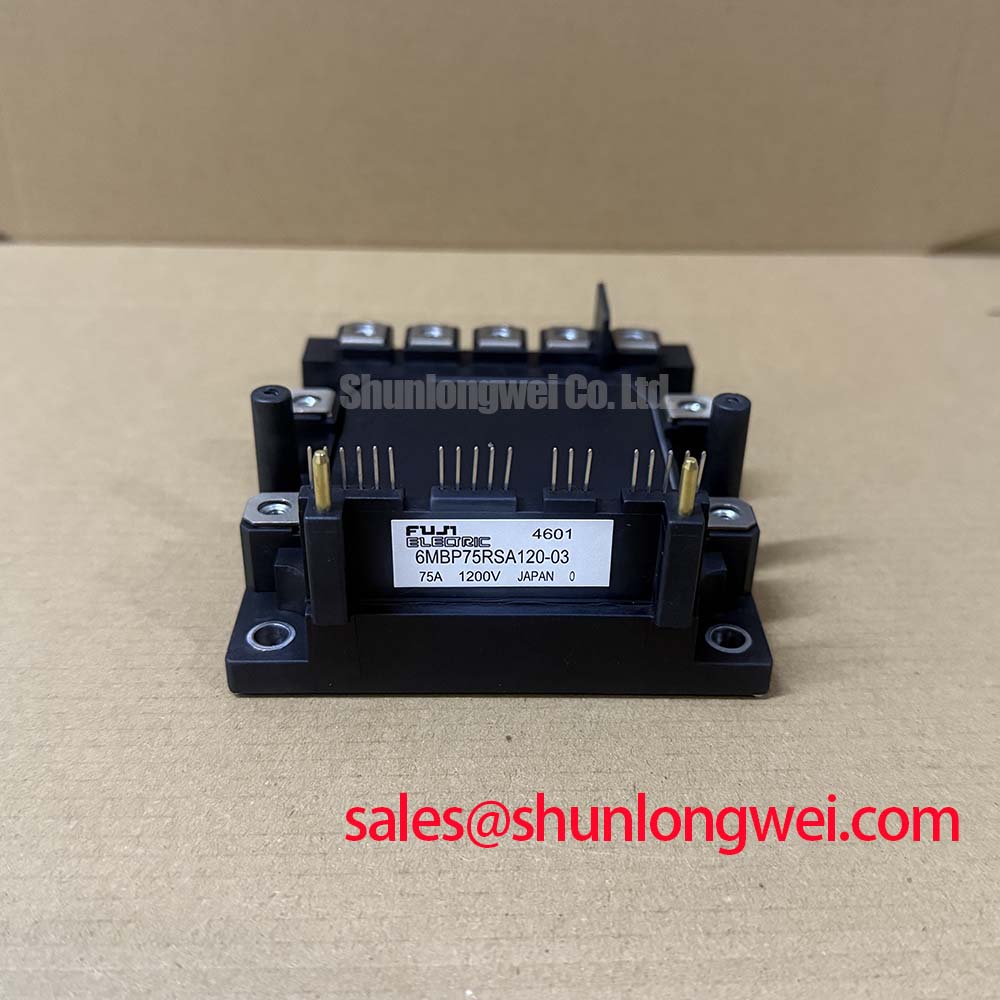
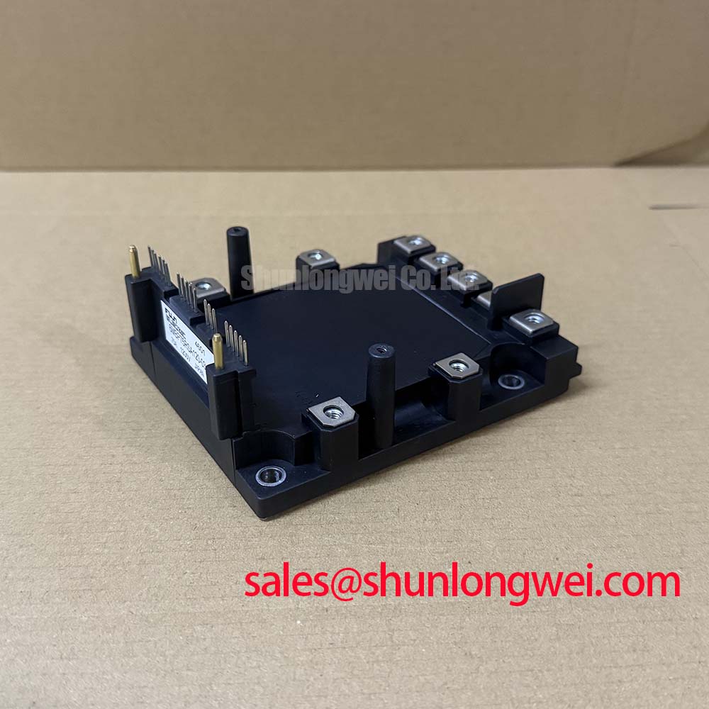
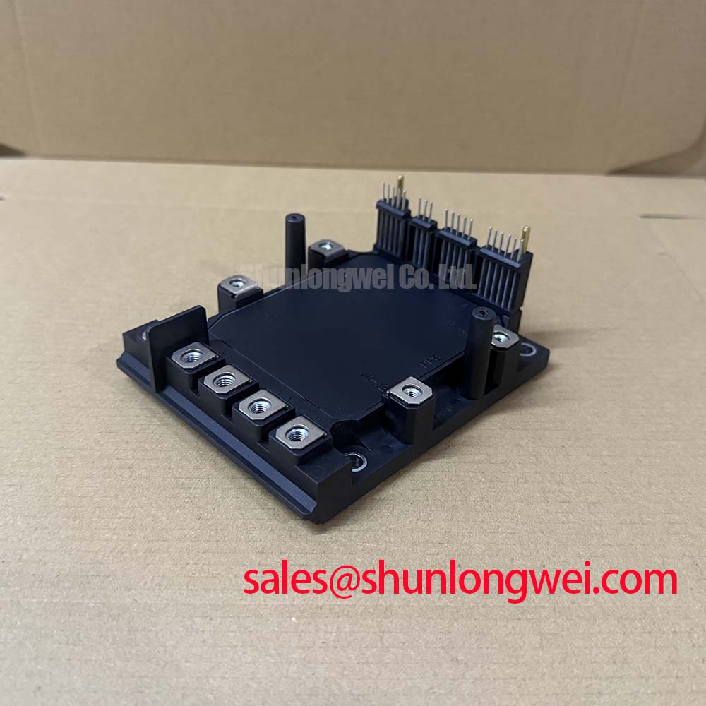

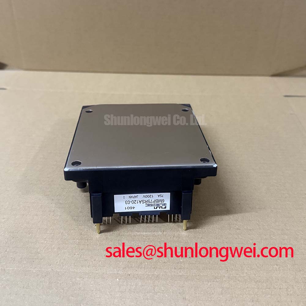
Technical Analysis: Redefining Reliability with the R-Series
The 6MBP75RSA120-03 represents a significant evolution in power density. At the heart of its Unique Value Proposition (UVP) is the integration of the fault-feedback mechanism. Unlike discrete setups where parasitic inductance between the IGBT and the driver can delay protection signals, the 6MBP75RSA120-03 utilizes on-chip sensing. To understand the engineering significance of its thermal resistance, you can visualize thermal resistance (Rth) as the width of a bridge; the lower the resistance, the more heat “traffic” can safely exit the silicon junction to the heatsink without causing a pile-up (thermal runaway).
By leveraging the IPM advantage, designers can bypass the tedious task of matching gate resistors to prevent parasitic turn-on. The internal drive circuits are pre-optimized to balance switching speed and EMI. Furthermore, the inclusion of integrated NTC thermistors allows for real-time temperature telemetry, enabling predictive maintenance protocols that traditional power stages cannot support without external sensors.
Optimized Application Scenarios
The 6MBP75RSA120-03 is technically optimized for environments where PCB real estate and high-speed reliability are paramount:
- Variable Frequency Drives (VFD): The 6-pack bridge configuration is perfectly suited for 3-phase motor control, reducing complex wiring in inverter stages.
- Uninterruptible Power Supplies (UPS): High switching frequency capability ensures clean sine-wave synthesis with minimal harmonic distortion.
- Industrial Air Conditioners: The integrated under-voltage and over-heat protection logic makes it resilient to the unstable power rails often found in industrial HVAC systems.
Best Match: Ideal for 3-phase motor applications up to 15kW requiring integrated protection logic and a compact 6-pack footprint.
6MBP75RSA120-03 Key Specifications
| Parameter Category | Feature | Typical Value |
|---|---|---|
| Absolute Maximums | Collector-Emitter Voltage (VCES) | 1200 V |
| Inverter Collector Current (Ic) | 75 A | |
| Operating Junction Temperature (Tj) | +150°C | |
| Electrical Characteristics | Saturation Voltage VCE(sat) | 2.3 V (typical) |
| Isolation Voltage | AC 2500V (1 min) | |
| Integrated Functions | Protection Types | OC, SC, UV, OH |
| Fault Output Signal | VFO (Logic Level) |
Engineer FAQ: Implementing the 6MBP75RSA120-03
Q1: Does this module require an external high-voltage gate driver?
No. The 6MBP75RSA120-03 features internal integrated IGBT drivers. You only need to provide the low-voltage logic supply (Vcc) and the PWM input signals.
Q2: How should I handle the VFO (Fault Output) signal?
The VFO is an open-collector output. It should be pulled up to the 5V logic supply. When a fault (like over-current or over-temperature) occurs, the module pulls this pin low, signaling the MCU to stop the PWM sequence immediately.
Q3: What is the recommended terminal torque for mounting?
For reliable operation and low thermal resistance, ensure the mounting screws are tightened to the datasheet-specified range (typically 2.5 to 3.5 N·m). Incorrect torque can lead to uneven cooling or mechanical stress on the internal ceramic substrate.
The 6MBP75RSA120-03 is engineered to streamline the transition from design to deployment by mitigating the traditional risks associated with gate drive isolation and fault sensing. Its robust 1200V/75A rating ensures it remains a staple for heavy-duty industrial automation where downtime is not an option.