Mitsubishi UM150CDY-10 Dual Darlington Module: Technical Overview and Specifications
UM150CDY-10 Mitsubishi Dual Darlington Module
Introduction and High-Power Specifications
The Mitsubishi UM150CDY-10 is a high-power dual Darlington transistor module designed for robust industrial switching. Rated at 500V and 150A, this device incorporates fast-recovery antiparallel diodes to manage inductive energy feedback. It serves as a dependable building block for medium-voltage AC and DC motor control circuits requiring isolated packaging. The electrical isolation simplified by the copper baseplate permits direct mounting on unified heatsinks, reducing overall assembly size.
- Core Specifications: 500V Collector-Emitter Voltage | 150A Collector Current | Isolated Copper Baseplate.
- Engineering Benefits: Reduced driver load through high current gain; simplified mechanical design via integrated isolation.
- Design Intent Answered: For engineers calculating thermal profiles under continuous 150A loads, the critical thermal parameters are analyzed below.
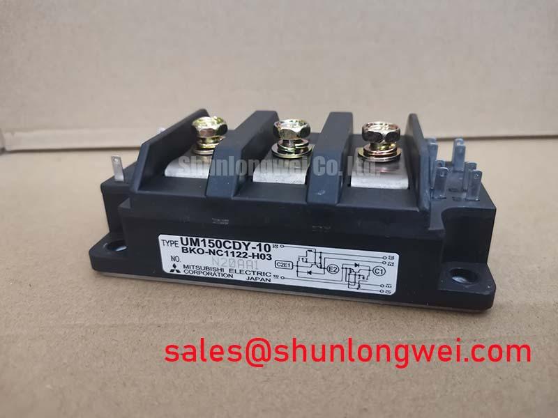
Explore our range of power semiconductors or view the product gallery below.


Technical Analysis of the Darlington Architecture
The UM150CDY-10 operates using a dual-stage Darlington configuration. This setup connects two bipolar junction transistors in series, allowing the primary transistor to amplify the control current for the secondary stage. Consequently, the module achieves a high DC current gain ($h_{FE} ge 75$), minimizing the drive current demanded from the gate control circuitry.
Thermal management represents a major factor in module longevity. The UM150CDY-10 features an isolated baseplate that provides 2500V AC isolation. This eliminates the need for separate ceramic insulators between the module and the heatsink.
Analogy: Think of thermal resistance like a narrow physical pipe. A lower thermal resistance rating acts as a wider pipe, allowing heat to escape rapidly from the junction to the ambient air. With a low junction-to-case thermal resistance ($R_{th(j-c)}$) of only 0.20°C/W for the transistor, the device handles peak power cycles while keeping the silicon junctions within safe limits.
To ensure reliable reverse-bias characteristics during inductive switching, the module integrates high-performance free-wheeling diodes. The forward voltage drop ($V_{EC}$) is kept to a maximum of 1.5V. This low drop prevents excessive power losses during the off-state. For modern alternatives, engineers can contrast these legacy bipolar structures with newer technologies like the Mitsubishi 7th Gen IGBT.
Industrial Application Fit
- AC & DC Motor Drives: The half-bridge equivalent layout facilitates motor direction control and speed modulation in variable speed systems.
- Uninterruptible Power Supplies (UPS): High current density ensures steady voltage regulation during power disruptions.
- Welding Converters: A high collector dissipation rating ($P_C = 620text{W}$) accommodates the rapid current spikes encountered in arc welding applications.
The UM150CDY-10 is best matched for legacy industrial inverter stages requiring simple drive circuits and high thermal conduction paths.
Key Specifications
| Parameter Group | Specification | Value |
|---|---|---|
| Absolute Maximum Ratings | Collector-Emitter Voltage (VEX) | 500 V |
| Continuous Collector Current (IC) | 150 A | |
| Maximum Power Dissipation (PC) | 620 W | |
| Junction Temperature Range (Tj) | -40 to +150 °C | |
| Electrical Characteristics | Collector-Emitter Saturation Voltage (VCE(sat)) | 2.0 V (max) |
| DC Current Gain (hFE) | 75 (min) | |
| Diode Forward Voltage (VEC) | 1.5 V (max) | |
| Thermal Characteristics | Junction-to-Case Thermal Resistance (Rth(j-c) Transistor) | 0.20 °C/W (max) |
| Junction-to-Case Thermal Resistance (Rth(j-c) Diode) | 0.90 °C/W (max) |
Engineer FAQ
Q1: Why choose a Darlington module over discrete transistors?
A1: The integrated configuration of the UM150CDY-10 provides pre-matched transistor pairs and free-wheeling diodes in a single isolated package. This reduces parasitic inductance and simplifies PCB layouts.
Q2: How does the isolated baseplate impact assembly space?
A2: Since the baseplate is electrically isolated up to 2500V AC, multiple modules can share a single metal heatsink. This layout reduces total system volume and mechanical assembly steps. To read about the thermal benefits of isolated packaging, see our post on isolated baseplates and reliability.
Q3: What is the significance of the $V_{EC}$ rating of the antiparallel diode?
A3: A low diode forward voltage drop ($V_{EC} le 1.5text{V}$) reduces conduction losses when the load current freewheels through the diode. For further engineering details, review how the free-wheeling diode dictates power system performance.
Solid Operational Reliability
The UM150CDY-10 provides a dependable switching platform for applications requiring high-current performance with simplified driver demands. Its robust thermal limits and integrated diode protection allow engineers to implement straightforward, long-lasting power switching circuits.