Mitsubishi PM50CSE120 IPM: A Technical Review and Application Guide
Mitsubishi PM50CSE120 Intelligent Power Module | 1200V 50A
Introduction and Core Highlights
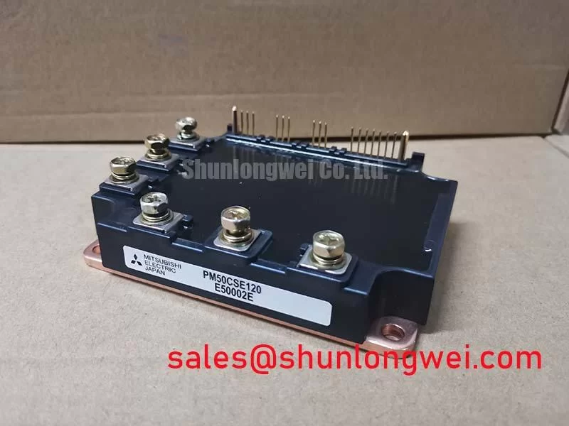
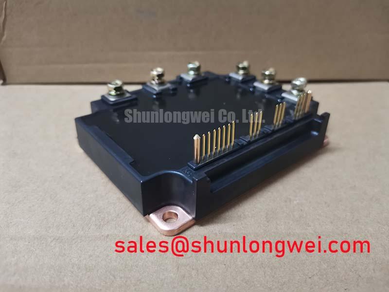
The Mitsubishi PM50CSE120 is a highly integrated C-Series Intelligent Power Module (IPM) that delivers robust performance by combining a three-phase IGBT inverter and a brake chopper circuit into a single package. Its core value lies in providing a comprehensive, protected power stage that simplifies design and enhances system reliability. This module integrates gate drive circuits and multiple protection functions, directly addressing the need for fault-tolerant motor control systems.
- Core Specifications: 1200V | 50A | VCE(sat) 2.7V (max)
- Key Advantages: Simplifies PCB layout and reduces component count; enhances system reliability with built-in protection.
For engineers designing compact variable frequency drives or servo systems, this integrated approach significantly shortens the development cycle by providing a pre-optimized and protected power stage.
Download Official Datasheet (PDF)
Technical Analysis of Integrated Features
The defining characteristic of the PM50CSE120 is its high level of integration. By co-packaging the 1200V IGBTs for the three-phase inverter and the brake chopper with their dedicated gate drivers and protection logic, the module eliminates many design challenges associated with discrete components. This architecture minimizes parasitic inductance between the driver and the IGBT gate, a common source of ringing and EMI in high-speed switching applications. The result is cleaner switching, improved efficiency, and more predictable performance, as detailed in the advantage of IPM structures.
A critical engineering benefit is the module’s comprehensive self-protection capability. It includes detection circuits for short-circuit (SC), over-temperature (OT), and control supply under-voltage (UV). The short-circuit protection is particularly vital for system survivability. Think of it like a fast-acting circuit breaker integrated directly at the chip level; it detects a dangerous current surge and safely shuts down the IGBTs in microseconds, preventing catastrophic failure. This built-in function removes the need for complex and potentially slower external monitoring and protection circuits, bolstering the overall robustness of the end application.

Optimized Application Scenarios
The specific features of the PM50CSE120 make it a strong candidate for several low-to-medium power applications:
- General Purpose Inverters: The module’s 50A rating and integrated brake chopper are well-suited for variable frequency drives (VFDs) in the 5.5kW to 7.5kW class, where dynamic braking is often required.
- AC Servo Drives: In precision motion control, rapid acceleration and deceleration are common. The module’s robust protection and optimized drivers provide the reliability needed to handle the dynamic loads of servo motors.
- Other Motor Controls: Any application requiring a compact, reliable, and easy-to-implement three-phase inverter with braking capabilities can benefit from this module’s all-in-one design.
This module is best matched for motor control systems requiring a robust, fault-tolerant power stage with a simplified design cycle and reduced assembly complexity.
Key Specification Parameters for PM50CSE120
| Absolute Maximum Ratings | ||
|---|---|---|
| Symbol | Parameter | Rating |
| VCES | Collector-Emitter Voltage | 1200V |
| ±IC | Collector Current (TC=25°C) | 50A |
| ±ICP | Collector Current (Peak) | 100A |
| PC | Collector Dissipation (TC=25°C) | 328W |
| Viso | Isolation Voltage (AC, 1 min.) | 2500Vrms |
| Electrical Characteristics (Inverter Part) | ||
| VCE(sat) | Collector-Emitter Saturation Voltage (IC=50A, Tj=125°C) | 2.7V (Max) |
| VEC | FWDi Forward Voltage (-IC=50A, Tj=125°C) | 2.9V (Max) |
| tsc | Short Circuit Withstand Time (Vcc=800V, Tj=125°C) | > 10µs |
Engineer’s FAQ
- How is thermal resistance specified for the PM50CSE120?
- The datasheet specifies the thermal resistance from junction to case, Rth(j-c), for both the IGBT and the freewheeling diode. This value is crucial for heatsink selection and thermal design. It acts as a measure of how efficiently heat can be transferred from the active semiconductor chip to the module’s baseplate, a key factor in ensuring the device operates within its safe temperature limits.
- What are the recommended operating conditions for the control supply voltage?
- The datasheet specifies a control supply voltage (VD) of 15V, with an allowable range of 13.5V to 16.5V for the protection circuits to operate correctly. Operating outside this range can compromise the under-voltage lockout (UV) protection and lead to improper gate drive levels. A stable, well-regulated 15V supply is essential for reliable operation.
- Does the PM50CSE120 require external short-circuit protection circuitry?
- No, one of the primary advantages of this Intelligent Power Module is its integrated short-circuit (SC) protection. The internal logic detects a short-circuit event and safely turns off the IGBTs, signaling a fault condition via the FO pin. This removes the need for external current sensing and high-speed comparator circuits for SC protection, which is a significant factor in preventing IGBT failures.
System Design Enablement
The PM50CSE120 provides a verified and robust power stage, enabling engineering teams to focus on system-level control and application-specific features rather than on the complexities of gate drive design and protection implementation. Its combination of 1200V IGBTs, a brake chopper, and built-in protective intelligence in a single component facilitates the development of more compact, reliable, and cost-effective motor control systems. For further insights into power module selection, consider exploring the differences between PIM and discrete IGBTs.