Infineon F4-150R06KL4 600V 150A Fourpack IGBT Module: Technical Overview and Application Guide
Infineon F4-150R06KL4 600V 150A Fourpack IGBT Module
The F4-150R06KL4 is an industrial H-bridge power module engineered in a compact EconoPACK™ 2 housing. Integrating four IGBT switches and fast-recovery freewheeling diodes into a single low-inductance package, it streamlines full-bridge power conversion designs. Engineers select this module to minimize parasitic layout inductance and simplify thermal management in bidirectional DC and AC switching systems.

- Core Ratings: 600V collector-emitter voltage, 150A continuous collector current (at TC = 80°C).
- Integrated Sensor: Built-in integrated NTC thermistor for precise real-time substrate temperature tracking.
- Key Benefits: Reduced assembly component count and symmetrical stray inductance across all four switching quadrants.
Technical Architecture and Thermal Performance
The primary value proposition of the F4-150R06KL4 is its integrated fourpack architecture. In high-power switching stages, discrete layout arrangements introduce uneven trace lengths. This layout discrepancy often leads to unbalanced voltage spikes during turn-off transients. By consolidating the entire full bridge onto an isolated copper baseplate, the module ensures symmetrical parasitic inductance across all bridge arms.
Thermal resistance from junction to case (RthJC) is rated at approximately 0.28 K/W per IGBT switch. Think of thermal resistance like a thermal pipeline: a wider, lower-resistance pipe allows heat generated during switching transitions to escape quickly into the heatsink, keeping internal die temperatures well within safe operating margins during continuous heavy loads.
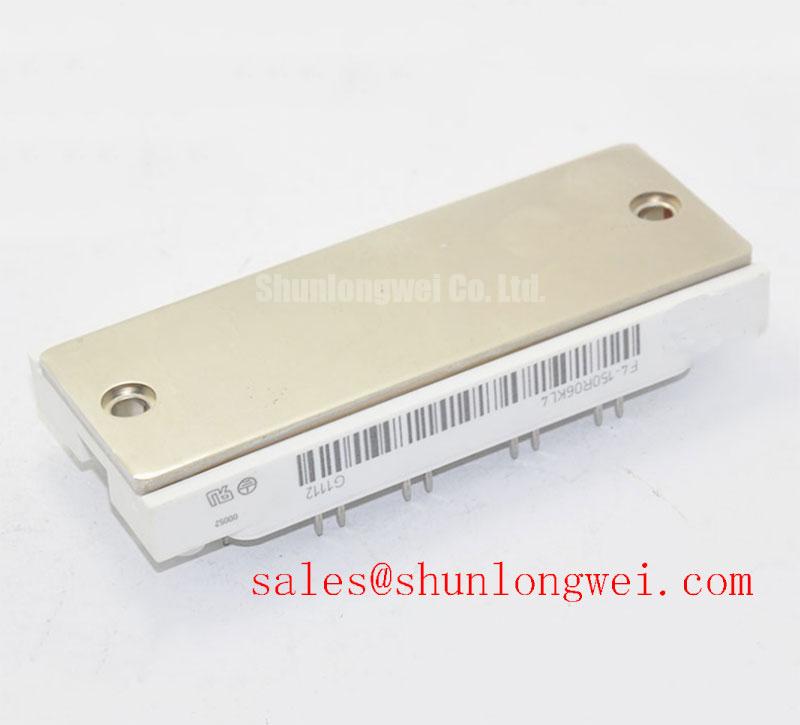

The integrated freewheeling diodes feature soft-recovery characteristics that dampen high-frequency ringing. Combined with a robust safe operating area (SOA), the silicon structure tolerates short-circuit events up to 10 µs under specified gate conditions, simplifying protective driver cutoff routines.
Optimized Application Scenarios
- Four-Quadrant DC Motor Drives: The native H-bridge topology handles bidirectional driving and regenerative braking without external bridge interconnects.
- Uninterruptible Power Supplies (UPS): Delivers efficient DC-AC inversion for 230V single-phase output stages with low total harmonic distortion.
- Switch-Mode Power Supplies (SMPS) & Battery Chargers: Operates smoothly in phase-shifted full-bridge DC-DC converters running at medium-to-high switching frequencies.
- Industrial Welding Systems: Handles rapid cyclic load steps while maintaining stable conduction performance through its copper baseplate.
Design Match: Optimized for 48V–400V DC-link systems requiring integrated four-switch control, compact footprints, and unified thermal sensing across the entire bridge.
Key Electrical and Thermal Specifications
| Parameter | Symbol | Rating / Value | Unit |
|---|---|---|---|
| Collector-Emitter Voltage (Tvj = 25°C) | VCES | 600 | V |
| Continuous DC Collector Current (TC = 80°C) | IC | 150 | A |
| Collector-Emitter Saturation Voltage (IC = 150A, Tvj = 125°C) | VCE(sat) | 2.20 (typ) | V |
| Short-Circuit Withstand Time (VGE ≤ 15V, VCC = 360V) | tsc | 10 | µs |
| Thermal Resistance, Junction to Case (per IGBT) | RthJC | 0.28 | K/W |
| Isolation Test Voltage (RMS, f = 50 Hz, t = 1 min) | VISOL | 2500 | V |
Engineering FAQ
Q: What are the main design advantages of selecting an H-bridge module over two half-bridge modules?
A: Choosing the F4-150R06KL4 over two discrete modules eliminates external DC-link interconnection straps. As analyzed in our guide on H-bridge vs half-bridge topologies, a single-housing fourpack reduces parasitic inductance, decreases board layout area, and ensures balanced heat distribution.
Q: What gate drive voltage is recommended for reliable operation?
A: Standard operation requires a nominal +15V on-state gate drive voltage to achieve rated VCE(sat). To prevent dv/dt-induced shoot-through in fast bridge switching, designers typically implement a negative turn-off bias (-5V to -8V) or an active Miller clamping circuit.
Q: What mounting precautions must be observed during heatsink installation?
A: Apply a uniform layer of thermal interface material (recommended thickness 50–100 µm). Tighten the mounting screws progressively in a crosswise sequence according to the manufacturer’s specified torque (3.0 to 6.0 Nm) to avoid substrate stress and ensure optimal thermal contact.
Procurement & Technical Support Overview
The F4-150R06KL4 offers an established four-quadrant switching platform for high-reliability industrial systems. Explore our catalog of power semiconductors or contact our technical team to verify full datasheet ratings and engineering specifications for your next power converter design.