A Technical Review of the Optrex DMF50174-ZNF-FW-17 Graphic LCD Module
“`html
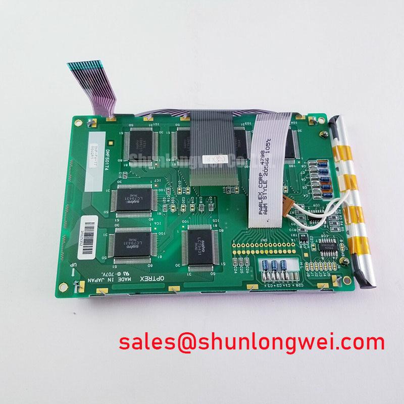
Optrex DMF50174-ZNF-FW-17 240×64 Graphic LCD Module
Introduction and Core Highlights
The Optrex DMF50174-ZNF-FW-17 is a monochrome graphic display module featuring an integrated controller to simplify system integration and reduce the workload on the host processor. This module renders sharp, high-contrast imagery suitable for instrumentation and operator interfaces where clarity is paramount.
- Core Specifications: 240 x 64 Dots | STN Negative Mode | White LED Backlight
- Key Advantages: Simplifies software development with an onboard controller, provides excellent readability for text and graphics.
By handling display memory and command execution internally, this module allows engineers to implement a graphical interface with minimal overhead.
Download the reference datasheet (PDF)

Technical Analysis
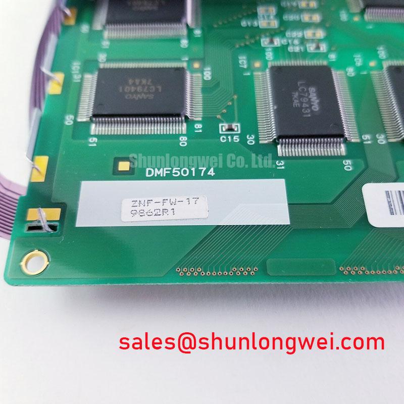
The engineering value of the DMF50174-ZNF-FW-17 is centered on its integrated Toshiba T6963C controller or an equivalent. This component acts as a dedicated graphics processor, managing the 8KB of display RAM and executing high-level commands sent from a host microcontroller. This architecture offloads tasks like cursor management, character generation, and bit-level pixel manipulation. For a system engineer, this means faster development cycles and the ability to use a less powerful, more cost-effective host MCU, as it is freed from the intensive task of constantly refreshing the display.
The display utilizes a transmissive, negative-mode Super-Twisted Nematic (STN) panel with a white LED backlight. This combination produces light pixels on a dark background, a format known for high perceived contrast in typical indoor and control room lighting conditions. The LED backlight provides a long operational life and stable brightness compared to older CCFL technologies, a key factor for equipment intended for long-term deployment. Proactive management of the backlight is crucial for ensuring product longevity.
Optimized Application Scenarios
- Industrial Control Panels: The 240×64 resolution is well-suited for displaying system status, menus, and soft key labels. The integrated controller simplifies connection to industrial controllers.
- Test and Measurement Equipment: Provides a clear, concise readout for numerical data, simple waveforms, and operational parameters. The module’s physical dimensions are compatible with standard rack-mount and benchtop instrument enclosures.
- Medical Instrumentation: Offers a reliable display for patient monitoring devices or diagnostic equipment where unambiguous data presentation is critical.
- Network Hardware: Can be used as a status panel on routers, switches, or servers to display IP addresses, traffic data, or error codes without requiring a full video interface.
Its datasheet-verified specifications make it an excellent match for systems requiring a robust, easily integrated monochrome graphical display.
Key Specifications of the DMF50174-ZNF-FW-17
| Parameter | Specification | |
|---|---|---|
| Display | Dot Pixels | 240 (W) x 64 (H) dots |
| Active Area | 132.0 (W) x 39.0 (H) mm | |
| LCD Type | STN / Negative / Transmissive | |
| Backlight | LED (White) | |
| Mechanical | Module Size | 180.0 (W) x 65.0 (H) x 12.5 (T) max mm |
| Weight | 155 g (Typ.) | |
| Electrical & Environmental | Logic Supply Voltage (VDD) | 5.0 V ± 5% |
| Operating Temperature | 0°C to +50°C | |
| Storage Temperature | -20°C to +60°C | |
Note: All specifications are based on the manufacturer’s reference datasheet for the DMF-50174ZNB-FW-BCN variant. Engineers must verify all parameters against the official documentation for their specific revision.
Engineer’s FAQ
1. What is the main benefit of the integrated T6963C controller?
The primary benefit is simplified system design. The controller manages the display RAM and command set for text and graphics modes, which means the host CPU only needs to send high-level commands over a standard 8-bit parallel interface, reducing software complexity and processing requirements.
2. What power supplies are required to operate the DMF50174-ZNF-FW-17?
The module requires a +5V logic supply (VDD) and a negative voltage for the LCD drive (VEE), which is generated by an onboard power supply circuit. The LED backlight also requires a separate supply, typically around +5V, connected to dedicated anode (A) and cathode (K) pins.
3. How is the display contrast adjusted?
Contrast is adjusted via an external potentiometer connected to the VSS, VDD, and Vo pins. The datasheet provides a reference circuit diagram showing a variable resistor (typically 10kΩ to 20kΩ) to allow adjustment of the LCD driving voltage (Vo) for optimal viewing clarity.
4. What defines the viewing angle for this module?
The reference datasheet specifies a 6 o’clock viewing direction. This means the display contrast is optimized for being viewed from slightly below the perpendicular axis, a common configuration for instruments mounted in a panel or on a desk. Understanding the basics of LCD core technology can help in selecting the right display for specific viewing requirements.
Enabling Clear and Reliable HMI Design
The DMF50174-ZNF-FW-17 provides a direct and efficient solution for integrating a graphical user interface into industrial-grade equipment. Its combination of a high-contrast monochrome display, a long-life LED backlight, and an intelligent onboard controller gives designers the necessary tools to create clear, reliable, and responsive operator interfaces.
“`