CM150E3U-24H Mitsubishi IGBT Module: A Technical Overview of the 1200V 150A Power Stage
CM150E3U-24H Mitsubishi IGBT Module | 1200V 150A Power Stage
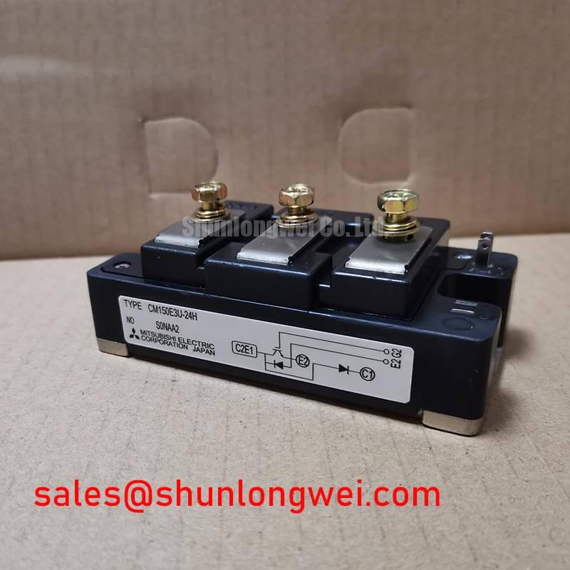
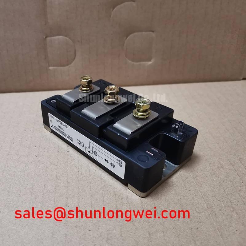
The CM150E3U-24H is an industrial-grade, high-performance IGBT module manufactured by Mitsubishi Electric. It is designed for high-power switching and power conversion systems. Utilizing an isolated baseplate design, this module delivers robust thermal management and high reliability under demanding load cycles. Delivering a collector-emitter voltage rating of 1200V and a continuous collector current of 150A, the CM150E3U-24H acts as a dependable building block for heavy-duty industrial applications.
Key Specifications:
- Collector-Emitter Voltage ($V_{CES}$): 1200V
- Collector Current ($I_C$): 150A (at $T_C = 25^circtext{C}$)
- Collector-Emitter Saturation Voltage ($V_{CE(sat)}$): 2.4V (typical)
Key Engineering Advantages:
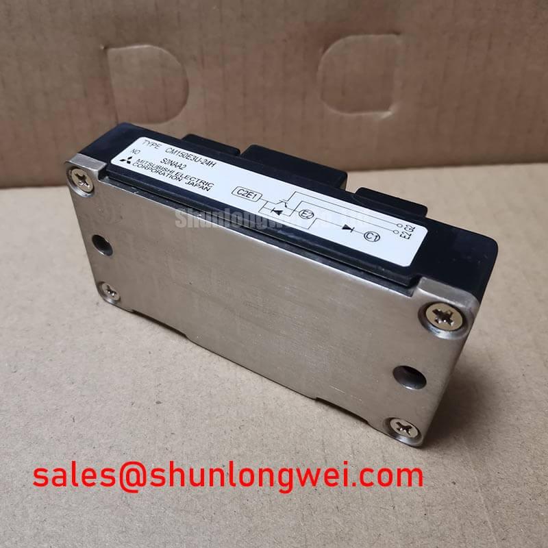
- Reduced Thermal Stress: The module features an isolated baseplate which simplifies heat sink mounting and ensures excellent thermal dissipation pathing.
- Optimized Efficiency: Low saturation voltage minimizes conduction losses, making it highly effective for high-power industrial inverter designs.
For detailed mechanical layouts, electrical limits, and safety margins, you can reference the manufacturer’s technical specifications.

High-Reliability Design and Thermal Performance
The CM150E3U-24H is engineered to balance switching speed and robust survivability in challenging electromagnetic environments. In high-power switching, parasitic inductance can induce transient voltage spikes that threaten the gate oxide layer. This module mitigates those risks with low internal package inductance, stabilizing switching waveforms. This helps designers manage electromagnetic interference (EMI) when configuring the gate drive circuitry.
Thermal management is critical to preventing IGBT failures. To help visualize this, you can think of thermal resistance as a narrow highway; a wider highway (lower thermal resistance) allows heat to flow away from the silicon junction much faster, preventing thermal congestion and subsequent device breakdown. The CM150E3U-24H achieves a low junction-to-case thermal resistance ($R_{th(j-c)}$) of approximately 0.16 $^circtext{C}/text{W}$ for the IGBT portion. This efficient thermal coupling prevents localized hot spots under demanding load cycles.
Additionally, the integrated free-wheeling diode features soft recovery characteristics. This is a critical factor in reducing transient high-frequency oscillations during turn-off phases. The soft-recovery diode limits voltage overshoot without requiring oversized snubber circuits, saving valuable board space and reducing bill-of-materials cost.
Target Applications
- Variable Frequency Drives (VFDs): Provides efficient AC motor speed control with minimal switching losses.
- Industrial Inverters: Serves as a rugged stage in solar inverters and uninterruptible power supplies (UPS).
- Welding Power Supplies: Handles high-current, low-duty-cycle thermal stresses reliably.
Conclusion: The CM150E3U-24H is best matched for high-current, 1200V-rated industrial motor control systems where thermal stability is paramount.
Key Technical Specifications
| Category | Parameter | Symbol | Value (Typical / Max) |
|---|---|---|---|
| Absolute Maximum Ratings | Collector-Emitter Voltage | $V_{CES}$ | 1200 V |
| Collector Current ($T_C = 25^circtext{C}$) | $I_C$ | 150 A | |
| Junction Temperature | $T_j$ | -40 to +150 $^circtext{C}$ | |
| Electrical Characteristics | Collector-Emitter Saturation Voltage | $V_{CE(sat)}$ | 2.4 V (Typical) / 3.2 V (Max) |
| Gate-Emitter Threshold Voltage | $V_{GE(th)}$ | 6.0 V to 7.5 V | |
| Thermal Characteristics | IGBT Thermal Resistance (Junction-to-Case) | $R_{th(j-c)}$ | 0.16 $^circtext{C}/text{W}$ (Max) |
| Isolation Voltage (AC, 1 minute) | $V_{isol}$ | 2500 V |
Engineer FAQ
Q1: What is the primary cause of collector-emitter saturation voltage ($V_{CE(sat)}$) drift?
A1: $V_{CE(sat)}$ values are temperature-dependent. At higher junction temperatures ($T_j$), the saturation voltage typically shifts upward due to carrier mobility degradation. Designers must calculate thermal dissipation boundaries using maximum $V_{CE(sat)}$ ratings rather than typical values to avoid thermal runaway.
Q2: Why is the isolated baseplate crucial in multi-module paralleling configurations?
A2: The isolated baseplate provides internal ceramic insulation rated for 2500V AC. This allows multiple CM150E3U-24H modules to be mounted on a single common heat sink without external isolation washers, minimizing thermal resistance interfaces and simplifying structural assembly.
Q3: How do the turn-on and turn-off switching characteristics affect gate resistor selection?
A3: Selecting the external gate resistor ($R_G$) requires balancing switching losses against voltage spikes ($dv/dt$). A lower $R_G$ speeds up switching but can introduce high inductive ringing, while a higher $R_G$ dampens spikes at the cost of elevated thermal dissipation during transitions.
The CM150E3U-24H provides power electronics designers with a stable, highly isolative, and thermally efficient solution for intermediate and high-power inverter switching, ensuring predictable operations in rugged industrial environments.
📊 Want me to compare this module’s thermal resistance specs with a dual or six-pack configuration to optimize your heat sink sizing?