FS820R08A6P2LB Technical Analysis: An Integrated B7 IGBT Module for High-Power Applications
FS820R08A6P2LB HybridPACK™ 2 IGBT Module | 800V 820A
Introduction and Core Highlights
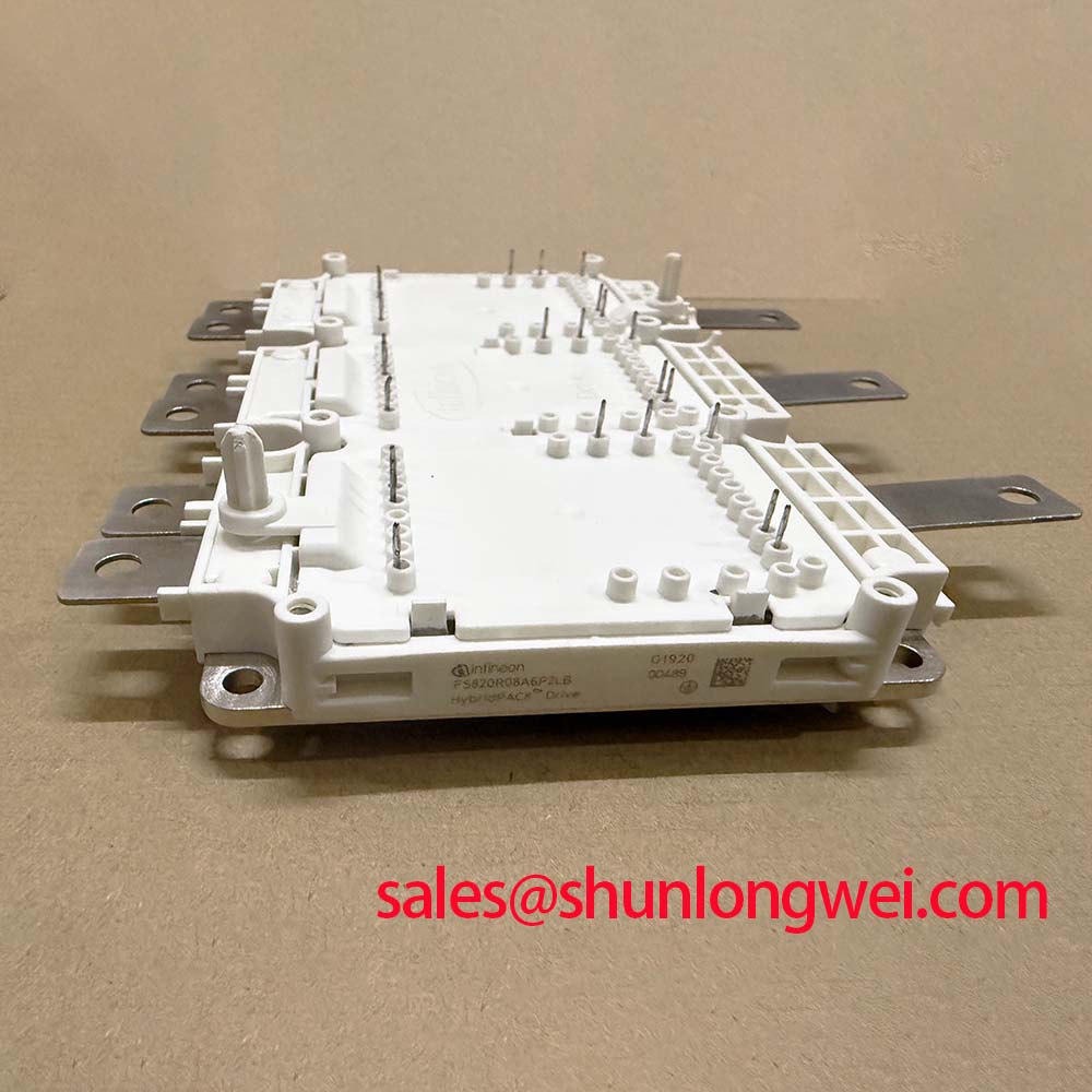
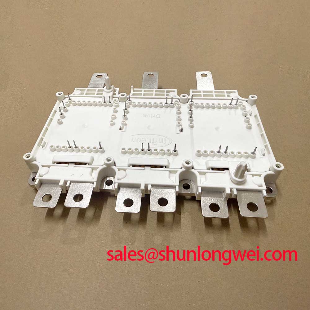
The Infineon FS820R08A6P2LB is a highly integrated power module that provides a complete B7 inverter stage within the robust, industry-proven HybridPACK™ 2 housing. This module leverages Infineon’s Trench/Fieldstop IGBT3 technology to deliver a balanced performance between conduction and switching losses, crucial for high-power motor drives requiring regenerative braking. The inclusion of a dedicated brake chopper simplifies system design and reduces component count, enabling more compact and reliable power conversion systems.
- Core Specifications: 800V | 820A (Inverter) / 470A (Chopper) | Tvj,op max 150°C
- Key Advantages: Integrated B7 topology simplifies system design, balanced loss profile enhances overall efficiency.
Download Official Datasheet (PDF)
Technical Analysis: Integrated Topology and Balanced Performance
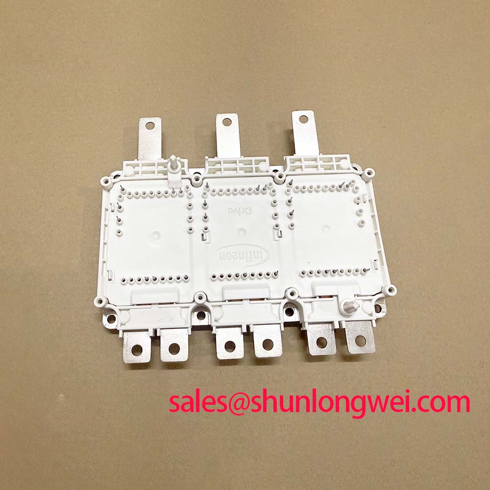
The primary engineering value of the FS820R08A6P2LB lies in its high level of integration. By incorporating a full sixpack inverter and a seventh brake chopper IGBT into a single HybridPACK™ 2 package, the module provides a complete drive and braking solution. This B7 configuration reduces the need for external components, minimizes DC-link stray inductance, and streamlines the assembly process. The result is a more compact, electrically efficient, and reliable power stage compared to designs using discrete modules for the inverter and brake chopper functions.
Performance is governed by the Trench/Fieldstop IGBT3 silicon, which offers a well-managed compromise between conduction losses (VCE(sat)) and switching losses (Eon, Eoff). Think of VCE(sat) as the rolling resistance of a tire; a lower value means less energy is wasted as heat during steady operation. Switching losses are akin to the energy used to accelerate and brake. This IGBT technology provides an effective balance, making it suitable for applications with variable speed and load profiles, such as industrial motor drives. Further enhancing system reliability, an integrated NTC provides a direct path for monitoring junction temperature.
Optimized Application Scenarios
The feature set of the FS820R08A6P2LB makes it a strong candidate for several demanding applications:
- Industrial Motor Drives: The integrated brake chopper is ideal for controlling motor deceleration and handling regenerative energy, a common requirement in servo drives and VFDs.
- Commercial and Agricultural Vehicles (CAV): The robust HybridPACK™ 2 package, with its established reliability, is well-suited for the harsh operating conditions found in CAV auxiliary drives.
- Uninterruptible Power Supplies (UPS): The module’s high current handling capability and efficient performance are beneficial for both online and line-interactive UPS topologies.
- Central Solar Inverters: The 800V rating and efficient thermal characteristics support the high-power DC-AC conversion stages in large-scale photovoltaic systems.
Its integrated B7 topology and robust thermal design make it a primary choice for high-power industrial motor drives requiring regenerative braking capability.
Key Specification Parameters
| Key Parameters for FS820R08A6P2LB | |
|---|---|
| Absolute Maximum Ratings | |
| Collector-Emitter Voltage (VCES) | 800 V |
| Continuous DC Collector Current (IC @ TC=100°C) | Inverter: 550 A / Chopper: 300 A |
| Operating Junction Temperature (Tvj op) | -40 to 150 °C |
| Inverter IGBT Characteristics (Tvj=25°C) | |
| Collector-Emitter Saturation Voltage (VCE(sat), typ. @ IC=820A) | 1.85 V |
| Thermal Characteristics | |
| Thermal Resistance, Junction-to-Case (Rth(j-c) per IGBT) | 0.10 K/W |
Engineer’s FAQ
- What is the primary benefit of the integrated brake chopper in the FS820R08A6P2LB?
- The integrated brake chopper provides a built-in mechanism for dissipating regenerative energy from a decelerating motor. This eliminates the need for a separate, external chopper module, which simplifies the overall system design, reduces assembly complexity, minimizes the footprint of the power electronics, and can lower stray inductance in the power circuit.
- What are the key considerations for mounting and ensuring proper thermal contact?
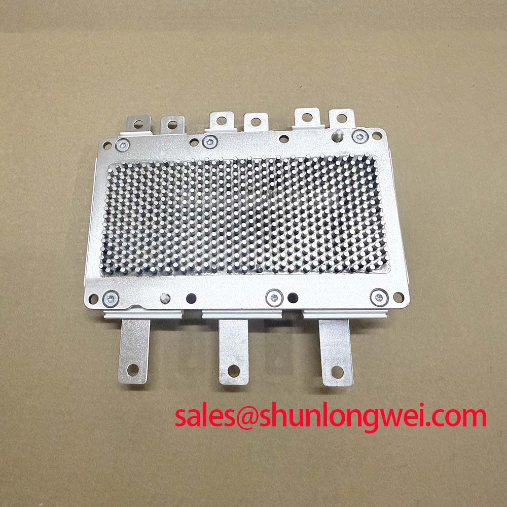
- According to the datasheet’s mounting instructions, it is critical to use a thermal interface material (TIM) between the module’s baseplate and the heatsink. The heatsink surface must be clean and flat. The module should be secured with the specified screw type (M5) and tightened to the recommended torque value (3 – 6 Nm) in the correct sequence to ensure even pressure distribution and optimal thermal contact. Incorrect mounting can lead to poor thermal performance and reduced module lifetime.
- How is the junction temperature monitored in this module?
- The module includes an integrated NTC (Negative Temperature Coefficient) thermistor. This sensor allows for direct monitoring of the module’s internal temperature, enabling the control system to implement over-temperature protection and ensure the device operates within its specified power semiconductors safe operating area.
- What does the Tvj op rating of 150°C imply for system design?
- A maximum operating junction temperature of 150°C provides significant headroom for designing robust systems. It allows for operation in demanding industrial environments with high ambient temperatures or enables more compact cooling solutions. The datasheet also specifies an overload temperature of 175°C, indicating a high level of thermal robustness for short-duration events.
Enabling Compact and Reliable Power Conversion
The design of the FS820R08A6P2LB directly addresses the need for higher power density and system reliability in modern inverters. By integrating a complete B7 power stage into a single, thermally efficient package, it allows engineers to develop more compact and robust motor control and power conversion systems, reducing both design complexity and assembly time. To explore more electronic components, visit our homepage.