Fuji 6MBI8L-120: An Integrated Power Solution for Compact Drives
## Fuji Electric 6MBI8L-120 IGBT Module for Compact Drives
The Fuji Electric 6MBI8L-120 is a Power Integrated Module (PIM) that provides a compact and reliable power stage solution for low-power motor control and inverter applications. Its key value proposition is the high level of integration, combining a three-phase diode bridge rectifier, a three-phase inverter, and a brake chopper circuit into a single M631 package. This significantly simplifies PCB layout and thermal management.
* **Core Specifications**: 1200V | 8A (Inverter) | VCE(sat) 3.4V (Max)
* **Key Advantages**: Integrated 6-in-1 design reduces component count and assembly complexity. The isolated baseplate simplifies heatsink mounting for effective thermal control.
* **Engineered for Efficiency**: This module is well-suited for systems where minimizing physical footprint and simplifying the bill of materials are critical engineering goals.
Download Official Datasheet (Link)
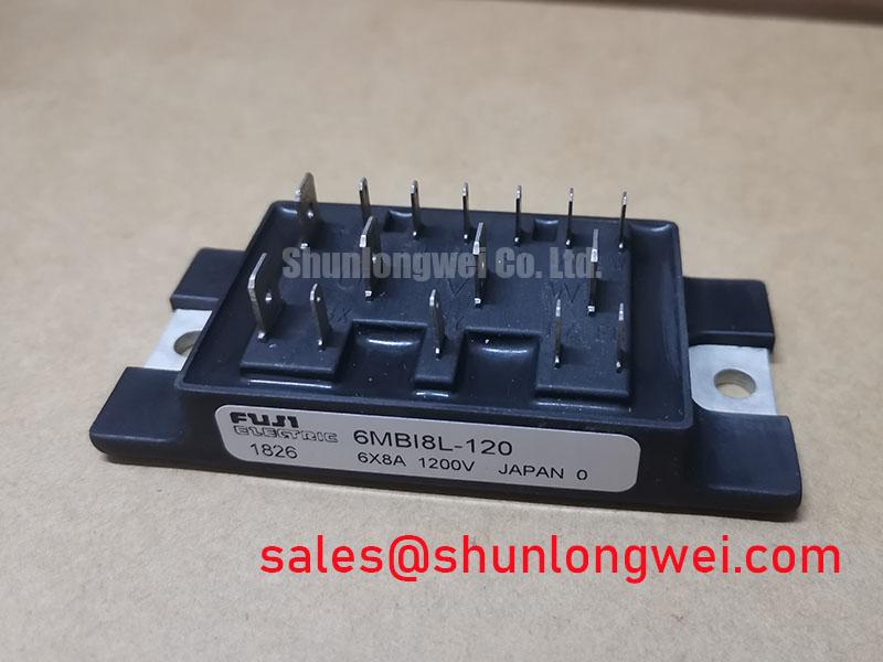


Technical Analysis of the 6-in-1 Integration
The primary engineering advantage of the 6MBI8L-120 is its “system-in-a-package” design. By housing the converter, brake, and inverter stages in one component, it eliminates the need for multiple discrete devices. This integration directly reduces parasitic inductance between power stages, which can otherwise lead to voltage overshoots and increased EMI. For designers, this means a more predictable power stage, a simplified assembly process, and a smaller overall system footprint.
The module’s thermal design is also a critical feature. The component features an isolated baseplate, allowing it to be mounted directly to a single heatsink without requiring additional insulating materials for each semiconductor. You can think of the thermal resistance from junction to case (Rth(j-c)) as the width of a pipe for heat to escape; a lower value means heat can be extracted more efficiently. The datasheet specifies this value, enabling engineers to perform accurate thermal calculations and select an appropriate cooling solution to maintain the junction temperature below its 150°C maximum rating. Understanding this thermal path is crucial for ensuring long-term operational reliability, a topic further explored in our guide to mastering IGBT thermal design.
Optimized Application Scenarios
The electrical characteristics of the 6MBI8L-120 make it a strong candidate for specific low-power applications operating from 400V AC lines.
* **Low-Power Variable Frequency Drives (VFDs)**: For motors under 1.5 kW used in pumps, fans, and conveyor systems, this PIM offers a complete power stage. The integrated brake chopper is particularly useful for managing regenerative energy during deceleration.
* **Small Servo Drives**: In automation and robotics, the module’s compact size and integrated nature are ideal for small, precise motor control where space is constrained.
* **Small Uninterruptible Power Supplies (UPS)**: The 1200V rating provides a sufficient safety margin for line-voltage-powered UPS systems, and the integrated rectifier and inverter simplify the core power conversion topology.
This PIM is a best-match for cost-sensitive industrial systems where compact design and simplified manufacturing are higher priorities than achieving ultra-low switching losses.
Key Specifications of the 6MBI8L-120
| Inverter Part – Absolute Maximum Ratings (Ta=25°C) | |
|---|---|
| Collector-Emitter Voltage (VCES) | 1200V |
| Gate-Emitter Voltage (VGES) | ±20V |
| Collector Current (IC) @ Tc=80°C | 8A |
| Collector Power Dissipation (PC) per IGBT | 45W |
| Electrical Characteristics (Tj=25°C) | |
| Collector-Emitter Saturation Voltage (VCE(sat)) @ IC=8A | 3.4V (Max) |
| Forward Voltage (VF) – FWD @ IF=8A | 3.0V (Max) |
| Thermal and Isolation Characteristics | |
| Operating Junction Temperature (Tj) | +150°C |
| Isolation Voltage (Visol) (AC, 1 min.) | 2500V |
Engineer’s FAQ for 6MBI8L-120
**1. What is the main benefit of using a PIM like the 6MBI8L-120 over discrete components?**
The main benefit is system simplification. A PIM integrates the rectifier, brake, and inverter into one package, reducing PCB space, minimizing assembly time, and lowering parasitic inductance that can cause EMI and voltage spikes in discrete layouts. This is a core concept discussed in our analysis of PIM vs. discrete IGBT strategies.
**2. How do I calculate the required heatsink for this module?**
To determine the appropriate heatsink, you must perform a thermal calculation. First, calculate the total power loss (conduction and switching losses) based on your application’s load profile. Then, use the Rth(j-c) (junction-to-case thermal resistance) from the datasheet to find the maximum allowable case-to-ambient thermal resistance (Rth(c-a)) for your heatsink, ensuring the junction temperature (Tj) remains below 150°C.
**3. Is the brake circuit always necessary?**
The integrated brake chopper is for managing regenerative energy, which occurs when a motor decelerates and acts as a generator. If your application (like a simple fan) does not involve rapid deceleration or overhauling loads, you may not need to connect an external braking resistor. However, the circuit is part of the module and available for applications that do require it.
**4. What is the typical VCE(sat) for this L-Series IGBT?**
The datasheet specifies a typical collector-emitter saturation voltage of 2.8V at the nominal collector current of 8A and Tj=25°C. The maximum rated VCE(sat) under the same conditions is 3.4V. This parameter is critical for calculating conduction losses. For more context, see our article on the quest for lower IGBT VCE(sat).
Enabling Compact Power Designs
The Fuji Electric 6MBI8L-120 provides a functionally complete power stage for low-power drive systems. Its value lies in the integration of six devices into a single, thermally efficient package. This approach allows engineers to accelerate development, reduce manufacturing complexity, and achieve a compact final product without compromising on the essential functions required for modern motor control.