Fuji 7MBP75RA120-01: Technical Review of a 1200V/75A 7-in-1 IPM Module
## Fuji 7MBP75RA120-01: 1200V/75A 7-in-1 IPM Module
Integrated Power Stage for Compact Motor Drives
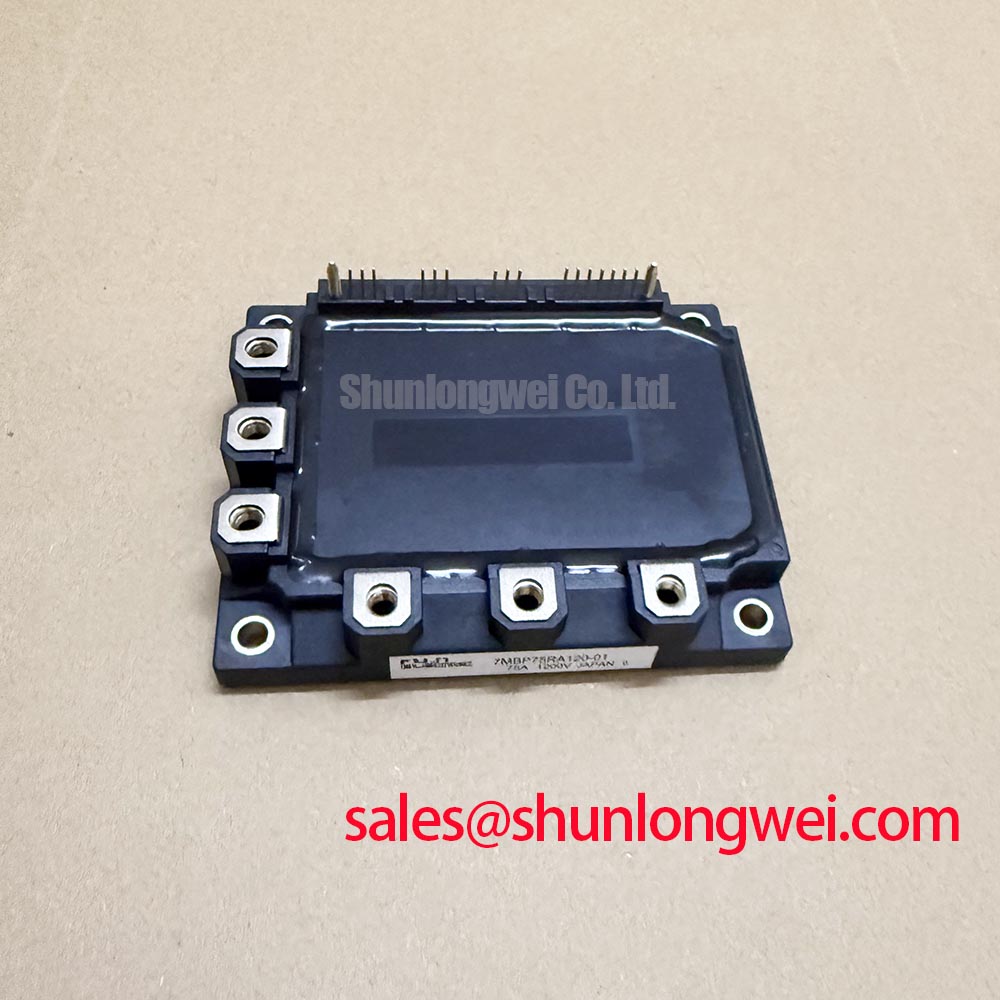
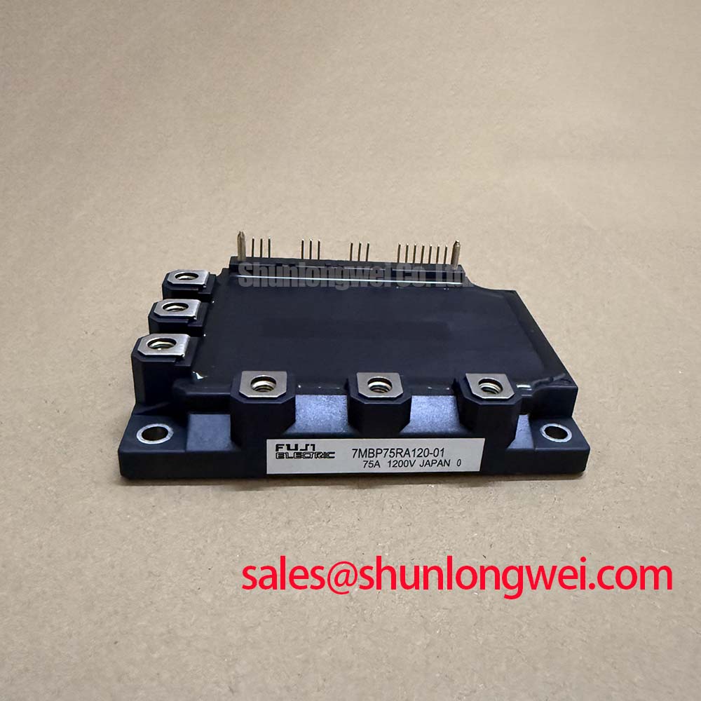
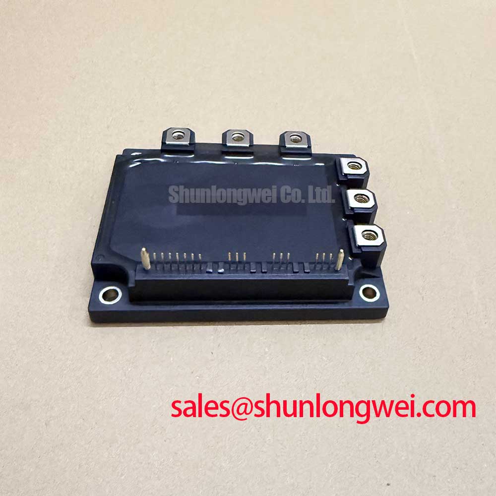
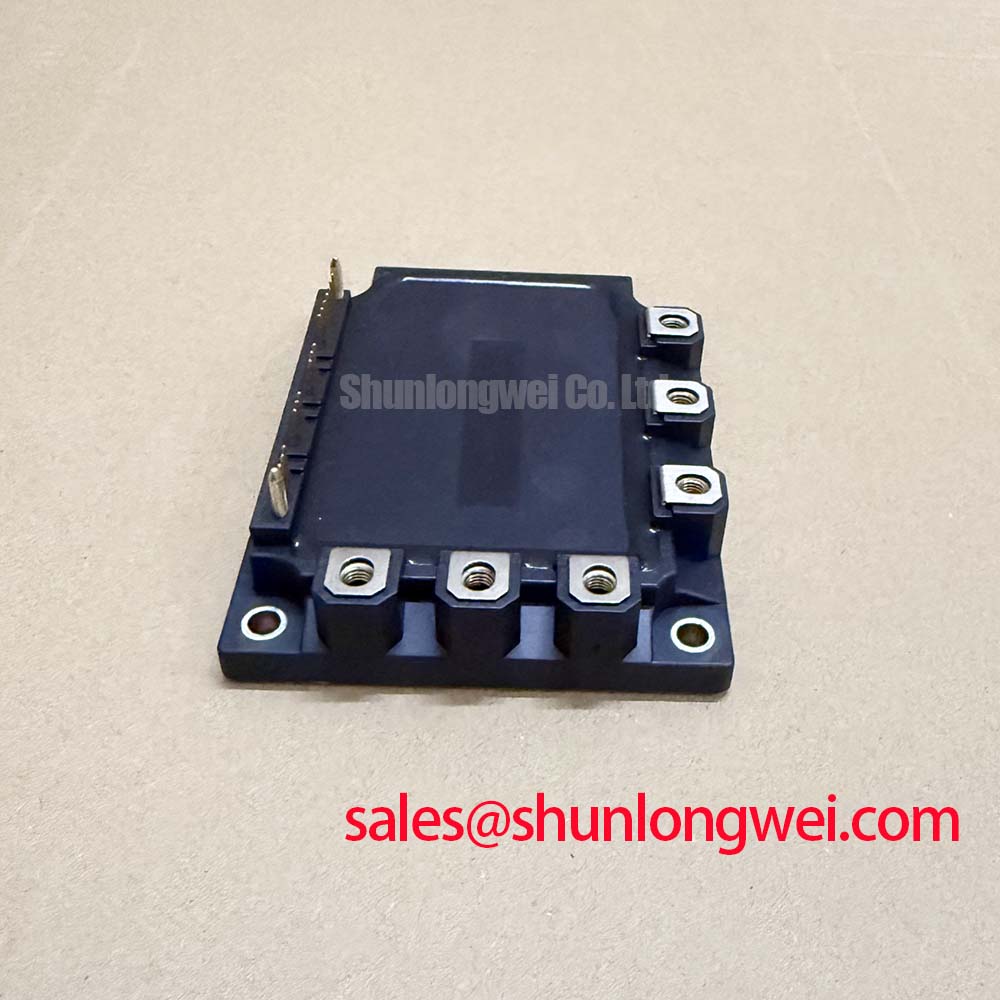
The Fuji Electric 7MBP75RA120-01 is a highly integrated Power Integrated Module (PIM) that combines a three-phase IGBT inverter, brake chopper, and input rectifier bridge into a single, efficient package. This integration is its core engineering value, simplifying the design of compact and reliable motor control systems. By consolidating the main power conversion stages, this module significantly reduces component count and simplifies PCB layout.
* **Core Specifications**: 1200V / 75A (Inverter); 1200V / 35A (Brake)
* **Key Engineering Value**: System simplification and enhanced reliability through 7-in-1 integration. This includes a three-phase converter, three-phase inverter, and brake chopper with an integrated NTC thermistor.
* **Operational Benefit**: The integrated NTC thermistor enables precise, real-time temperature monitoring for implementing robust over-temperature protection.
Download the Official 7MBP75RA120-01 Datasheet (PDF)
Technical Analysis of the 7-in-1 Architecture
The primary advantage of the 7MBP75RA120-01 is its high level of integration. A conventional motor drive design using discrete components requires a separate rectifier bridge, six IGBTs with six freewheeling diodes for the inverter, another IGBT/diode pair for the brake chopper, and an NTC thermistor. This module consolidates all these into one component, which reduces manufacturing complexity and minimizes stray inductance between stages, a common source of voltage overshoot and EMI in high-frequency switching circuits.
A key parameter for system reliability is the junction-to-case thermal resistance (Rth(j-c)). For the inverter IGBT in this module, the Rth(j-c) is specified at a maximum of 0.73°C/W. This value is critical for thermal design. You can think of thermal resistance as the narrowness of a pipe; a lower value represents a wider pipe that allows heat to escape the semiconductor chip more easily. This efficient heat transfer is crucial for preventing the device from exceeding its maximum junction temperature of 150°C and ensures long-term operational stability.
Optimized Application Scenarios
The specific characteristics of the 7MBP75RA120-01 make it suitable for several power conversion applications:
* **Variable Frequency Drives (VFDs):** The all-in-one nature, including the input rectifier and brake chopper, makes it a complete power core for AC motor control.
* **Industrial Servo Drives:** The integrated 35A brake chopper is well-suited for managing the regenerative energy produced when high-inertia loads are decelerated rapidly.
* **Pump and Fan Control:** In applications where braking is less critical, the inverter section provides robust, reliable control for three-phase motors.
* **General-Purpose Inverters:** The module serves as a compact and reliable building block for developing small to medium-power inverters.
This module is best matched for motor control systems up to 15 kW that demand a compact footprint, simplified assembly, and integrated thermal monitoring.
Key Specifications of the 7MBP75RA120-01
| Absolute Maximum Ratings (T_c = 25°C) | ||
|---|---|---|
| Parameter | Inverter / Brake Part | Converter Part |
| Collector-Emitter Voltage (V_CES) | 1200V | N/A |
| Collector Current (I_C) | 75A (DC), 150A (Pulsed) | N/A |
| Repetitive Peak Reverse Voltage (V_RRM) | N/A | 1200V |
| Forward Current (I_F) | N/A | 75A |
| Collector Power Dissipation (P_C) | 430W (per IGBT) | N/A |
| Operating Junction Temperature (T_j) | +150°C | |
| Electrical & Thermal Characteristics (T_j = 25°C unless noted) | ||
| Parameter | Condition | Value (Typ. / Max) |
| Collector-Emitter Saturation Voltage (V_CE(sat)) | I_C = 75A, V_GE = 15V | 2.3V / 2.8V |
| Forward Voltage (V_F) | I_F = 75A | 2.1V / 2.6V |
| NTC Thermistor Resistance (R_th) | T_c = 25°C | 5 kΩ |
| Thermal Resistance, Junction-to-Case (R_th(j-c)) | Inverter IGBT | 0.29°C/W / 0.73°C/W |
Note: Specifications are sourced from the official Fuji Electric datasheet. Please refer to the datasheet for complete and up-to-date information.
Engineer’s FAQ for the 7MBP75RA120-01
- What are the primary benefits of using a PIM like the 7MBP75RA120-01 versus a discrete IGBT design?
- Using this PIM significantly simplifies system design. It reduces the number of components on the bill of materials, shrinks the required PCB space, and lowers assembly costs. The controlled internal layout also minimizes parasitic inductance, which improves electrical performance and reliability compared to a discrete solution with long trace lengths. Learn more about the impact of parasitic inductance on IGBT performance.
- How do I use the integrated NTC thermistor for thermal protection?
- The module includes an NTC thermistor with a resistance of 5 kΩ at 25°C and a B-constant of 3375K. You can connect this thermistor to an analog input on your microcontroller (often via a simple voltage divider circuit) to continuously monitor the module’s case temperature. This data allows your control firmware to trigger alarms, reduce power output, or shut down the system if the temperature exceeds safe operational limits, a crucial step for ensuring IGBT module safety.
- What considerations are needed for heatsink selection?
- Heatsink selection requires calculating the total power loss (conduction and switching losses) under your specific operating conditions. Using the module’s specified thermal resistance from junction to case (R_th(j-c)) and the thermal resistance of your chosen thermal interface material (R_th(c-s)), you can determine the maximum allowable heatsink-to-ambient thermal resistance (R_th(s-a)) to keep the IGBT junction temperature below its 150°C maximum. Accurate IGBT thermal design is essential for system reliability.
- What are the gate drive requirements for this module?
- The datasheet recommends a gate drive voltage (V_GE) of +15V for turn-on and 0V for turn-off. The typical gate-emitter threshold voltage (V_GE(th)) is 5.5V. It is important to use a gate driver capable of supplying sufficient peak current to charge and discharge the gate capacitance efficiently to achieve the specified switching times and minimize losses.
Enabling Compact and Reliable Power Conversion
The 7MBP75RA120-01 offers a robust, verified solution for engineers tasked with developing power conversion systems under pressure to reduce size and cost without compromising reliability. By integrating the core components of a motor drive into a single package, this module streamlines the development process, from initial design and layout to final assembly. It allows engineering teams to focus on system-level control and performance, backed by a thermally efficient and pre-optimized power stage.