Fuji 7MBR100SB060-50: A Deep Dive into the 7-in-1 IGBT for Compact Drives
Fuji 7MBR100SB060-50 7-in-1 IGBT Module | 600V 100A
Integrated Power Stage for Compact Drive Systems
The Fuji Electric 7MBR100SB060-50 is a highly integrated Power Integrated Module (PIM) that consolidates a complete three-phase inverter, brake chopper, and converter rectifier into a single, compact S-Series package. This 7-in-1 topology provides a streamlined solution for engineers developing space-constrained motor drives and power conversion systems. By integrating these critical stages, the module significantly reduces component count and simplifies PCB layout, addressing the need for higher power density in modern industrial equipment.
- Core Specifications: 600V | 100A (Inverter) | 7-in-1 PIM
- Key Advantages: Simplifies system assembly, enables precise thermal monitoring.
For complete specifications, refer to the official documentation.
Download Official Datasheet (PDF)
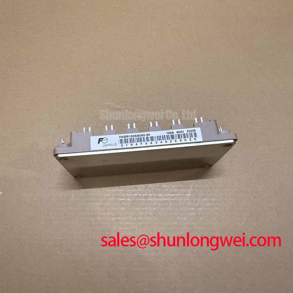

Technical Analysis of the 7-in-1 Integrated Design
The primary engineering value of the 7MBR100SB060-50 lies in its high level of integration. By housing the converter diodes, brake IGBT with freewheeling diode, and the six-pack inverter IGBTs in one module, it eliminates the need for multiple discrete packages. This PIM vs. discrete IGBT approach reduces the complexity and duration of the manufacturing assembly process. Furthermore, the short, optimized internal connections minimize stray inductance, which is a common source of voltage overshoot and EMI in high-frequency switching applications.
Effective thermal management is fundamental to power module reliability. This module features a low thermal resistance from junction to case (Rth(j-c)) of 0.26 °C/W for each inverter IGBT. Think of thermal resistance as the width of a pipe for heat; a lower value represents a wider pipe, allowing heat to escape more efficiently from the active silicon to the heatsink. This efficiency, combined with a maximum junction temperature rating of 150°C, provides a solid foundation for robust operation. The inclusion of an integrated NTC thermistor provides a direct feedback mechanism for monitoring the module’s operating temperature, enabling a control system to implement over-temperature protection.


Optimized Application Scenarios
The characteristics of this module make it a strong candidate for several power conversion applications:
- AC Motor Drives (VFDs): The 7-in-1 configuration provides all necessary power components for a standard VFD front-end and inverter stage, making it ideal for compact and cost-effective designs.
- Servo Amplifiers: Its high integration level is valuable in servo systems where board space is at a premium and reliability is critical for precision motion control.
- Uninterruptible Power Supplies (UPS): The module’s converter and inverter sections are well-suited for the rectification and inversion stages in online UPS systems.
- General Purpose Inverters: The robust voltage and current ratings support a wide range of general-purpose power conversion tasks.
This module is an optimal match for power systems up to 30kW requiring high integration density and robust thermal feedback capabilities.
Key Specifications of the 7MBR100SB060-50
| Parameter | Inverter Section | Brake Section | Converter Section |
|---|---|---|---|
| Collector-Emitter Voltage (Vces) | 600V | 600V | N/A |
| Continuous Collector Current (Ic) @ Tc=80°C | 100A | 50A | N/A |
| Collector-Emitter Saturation Voltage (VCE(sat)) Typ. | 2.1V @ 100A | 2.2V @ 50A | N/A |
| Repetitive Peak Reverse Voltage (VRRM) | N/A | N/A | 1200V |
| Forward Current (IF) | N/A | N/A | 100A |
| Operating Junction Temperature (Tj) | +150°C | ||
| Isolation Voltage (Viso) | 2500V (AC for 1 minute) | ||
Engineer’s FAQ
1. What makes the 7MBR100SB060-50 suitable for compact motor drives?
Its 7-in-1 integrated design combines the input rectifier, brake chopper, and output inverter into a single module. This reduces the required PCB area and simplifies the bill of materials, which are critical factors for creating compact motor drive systems.
2. What is the primary consideration when designing a heatsink for this module?
The key is to ensure the total thermal resistance from the module’s baseplate to the ambient air keeps the junction temperature (Tj) below the 150°C maximum rating under worst-case load conditions. You must calculate the total power dissipation from all active components (inverter, brake, and rectifier) and use the module’s specified thermal resistance values to select an appropriate heatsink and airflow solution.
3. How is the integrated NTC thermistor used for protection?
The built-in NTC thermistor provides real-time temperature feedback from the module’s baseplate. It has a nominal resistance of 5 kΩ at 25°C. A microcontroller or control circuit can monitor this resistance to infer the module’s temperature, triggering a fault condition, reducing output power, or initiating a system shutdown if it exceeds a safe operating limit.
4. What is the recommended gate-emitter voltage (VGE) for driving the IGBTs?
The datasheet specifies a recommended VGE of +15V ±10% for turning the IGBTs on. The gate-emitter threshold voltage, VGE(th), is between 5.0V and 8.0V. Using a stable +15V drive ensures the IGBTs are fully saturated to minimize conduction losses.
Enabling System Miniaturization and Reliability
The 7MBR100SB060-50 offers a practical and efficient path to developing compact power conversion systems without compromising on thermal performance. Its consolidation of key power stages into a single, thermally-aware component allows design teams to reduce system complexity, streamline assembly, and build reliable, power-dense motor drives and inverters. For further reading on related IGBT topics, explore our guide to preventing IGBT latch-up.