Fuji 7MBR100U4B120-50: A Technical Analysis of the 1200V 100A 7-in-1 IGBT Module
Fuji 7MBR100U4B120-50 IGBT Module: 1200V 100A 7-in-1
Integrated Power Solution for Compact Motor Drives
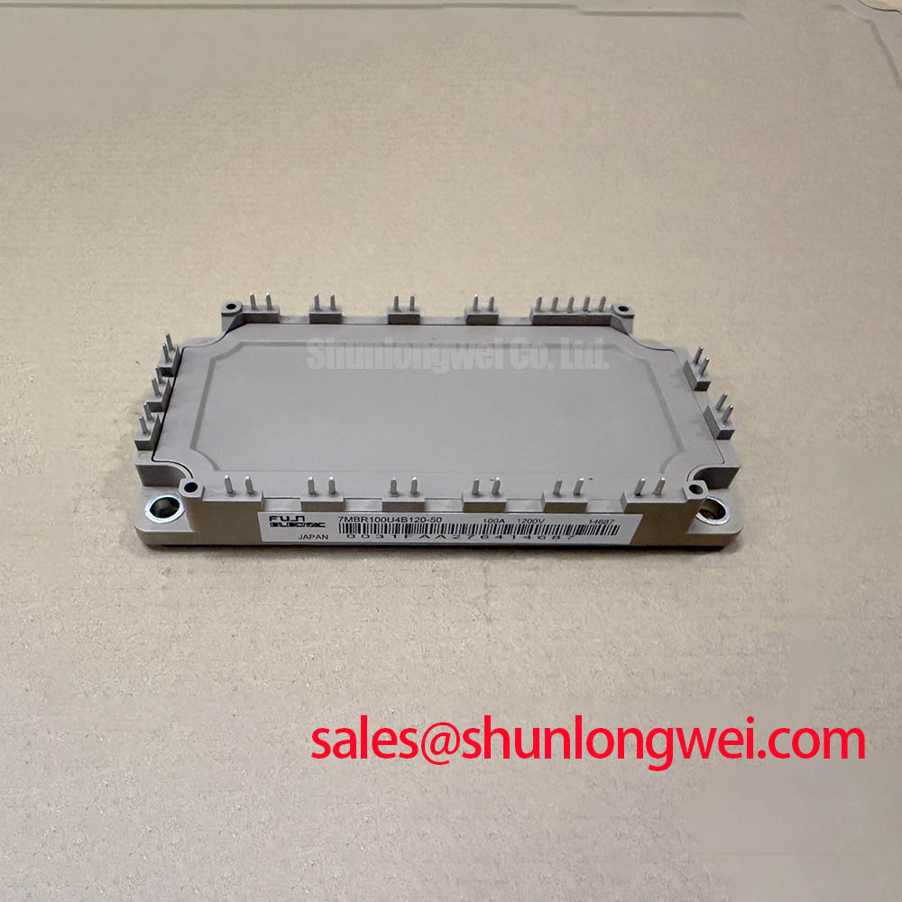
The Fuji Electric 7MBR100U4B120-50 is a 7-in-1 Power Integrated Module (PIM) that consolidates a three-phase inverter, brake chopper, and rectifier into a single, compact package. This high level of integration provides a streamlined solution for power conversion systems by minimizing component count and simplifying PCB layout. It is engineered to balance performance and reliability, featuring an integrated NTC thermistor for real-time temperature monitoring, crucial for robust system protection.
- Core Specifications: 1200V | 100A | 7-in-1 PIM with Brake Chopper
- Key Advantages: Reduces component count and simplifies assembly, enables precise thermal monitoring.
- Primary Function: Ideal for creating compact and efficient power stages in motor control systems.
Download Official Datasheet (PDF)

Technical Analysis: Integration and Thermal Management
The defining characteristic of the 7MBR100U4B120-50 is its 7-in-1 configuration. By integrating the six IGBTs and freewheeling diodes for a three-phase inverter with a seventh IGBT/FWD pair for a brake chopper, the module significantly reduces the physical footprint of the power electronics stage. This consolidation minimizes the length of electrical connections between the inverter and brake circuits, which can help lower stray inductance—a critical factor in reducing voltage overshoot during high-frequency switching. For designers, this means a more straightforward layout, fewer assembly steps, and potentially improved electromagnetic compatibility (EMC) performance.
Effective thermal management is fundamental to the reliability of any power module. The inclusion of an NTC thermistor inside the 7MBR100U4B120-50 provides a direct method for monitoring the module’s internal temperature. The NTC thermistor acts like a built-in thermometer for the module’s core; its resistance changes predictably with temperature. This allows the system’s controller to implement precise over-temperature protection, preventing the device from exceeding its maximum junction temperature of 150°C as specified in the datasheet. This feature is a key enabler for building durable systems that can operate reliably under demanding load conditions.


Optimized Application Scenarios
The specific topology of this module makes it a strong candidate for several applications:
- AC Motor Drives (VFDs): The integrated inverter and brake chopper are essential for controlling motor speed and managing regenerative energy during deceleration, common in conveyor and elevator systems.
- Servo Drives: Provides the necessary power stage for precise motion control applications where dynamic braking is a frequent requirement.
- Uninterruptible Power Supplies (UPS): The module’s components can be utilized for both the inverter output stage and managing the DC bus energy.
- General Purpose Inverters: The all-in-one design simplifies the development of various power conversion units where space and assembly efficiency are priorities.
This module is best matched for motor control applications up to approximately 45kW that require an integrated braking circuit for energy management.
Key Specifications of the 7MBR100U4B120-50
| Absolute Maximum Ratings (Tc = 25°C) | |
|---|---|
| Collector-Emitter Voltage (Vces) | 1200V |
| Gate-Emitter Voltage (Vges) | ±20V |
| Collector Current (Ic) (Inverter & Brake) | 100A (Tc=80°C) |
| Forward Current (IF) (Diode) | 100A (Tc=80°C) |
| Max Power Dissipation (Pc) (Inverter) | 480W |
| Operating Junction Temperature (Tj) | +150°C |
| Electrical Characteristics (Tj = 25°C) | |
| Collector-Emitter Saturation Voltage (Vce(sat)) – Inverter (Ic=100A) | 2.2V (Typ), 2.7V (Max) |
| Collector-Emitter Saturation Voltage (Vce(sat)) – Brake (Ic=100A) | 2.4V (Typ), 3.0V (Max) |
| Forward Voltage (Vf) – Diode (If=100A) | 2.1V (Typ), 2.6V (Max) |
| Thermal Resistance (Rth(j-c)) – Inverter IGBT | 0.26 °C/W (Max) |
| NTC Thermistor Resistance (R25) | 5.0 kΩ (25°C) |
Engineer’s FAQ
1. What is the primary advantage of the 7-in-1 configuration in the 7MBR100U4B120-50?
The main advantage is system simplification. It integrates the three-phase inverter and brake chopper into a single module, which reduces the number of power components, simplifies the PCB layout, shortens assembly time, and can lower the overall system cost compared to a solution using discrete components.
2. How should the integrated NTC thermistor be used for thermal protection?
The NTC thermistor provides a resistance value that corresponds to the module’s temperature. This should be connected to a monitoring circuit, typically using a voltage divider read by a microcontroller’s ADC. By referencing the R-T curve in the datasheet, the controller can accurately calculate the module temperature and trigger a fault or reduce power if it approaches the maximum operating limit of 150°C.
3. What are the recommended gate drive voltage conditions for this module?
The datasheet specifies the electrical characteristics with a gate-emitter voltage (Vge) of +15V for turn-on. The absolute maximum Vges rating is ±20V. For stable operation and to avoid accidental turn-on, a negative gate voltage (e.g., -5V to -15V) is typically recommended for turn-off, although the datasheet parameters are characterized with Vge = 0V. An appropriate gate driver is essential.
4. What is the short-circuit withstand time for the IGBTs in this module?
The datasheet specifies a minimum short-circuit withstand time (Tsc) of 10 microseconds under the conditions of Vcc = 600V, Vge ≤ 15V, and Tj = 125°C. This is a critical parameter for ensuring system robustness against fault conditions. Understanding such limits is vital to prevent catastrophic IGBT failures.
System Design Enablement
The 7MBR100U4B120-50 provides engineers with a highly integrated building block for power conversion. Its combination of a full three-phase inverter and brake chopper within a single, thermally-monitored package allows for the design of more compact, reliable, and cost-effective motor drives and inverters. This integration streamlines both the design and manufacturing processes, enabling faster development cycles for industrial power systems.