Fuji 7MBR50SA060-50: A Technical Review of the 7-in-1 Integrated IGBT Module
Fuji 7MBR50SA060-50 IGBT Module | 600V 50A 7-in-1 Pack
Introduction and Core Highlights
The Fuji Electric 7MBR50SA060-50 is a highly integrated IGBT module that consolidates a complete three-phase inverter and a brake chopper circuit into a single compact package. This 7-in-1 configuration streamlines the design of low-to-medium power motor control systems by minimizing external component count and simplifying PCB layout. An integrated NTC thermistor provides a direct method for real-time temperature monitoring, enabling robust over-temperature protection and enhancing overall system reliability.
- Core Specifications: 600V | 50A | 7-in-1 Configuration
- Key Advantages: Reduced system component count, integrated thermal sensing
Download Official Datasheet (PDF)
Technical Analysis of Integrated Design
The primary engineering value of the 7MBR50SA060-50 lies in its high level of integration. By incorporating six IGBTs in a three-phase bridge, a seventh IGBT for a dynamic brake circuit, and corresponding free-wheeling diodes, the module replaces numerous discrete components. This approach directly reduces assembly complexity and shrinks the overall footprint of the power stage. For design teams, this translates to faster development cycles, a simplified Bill of Materials (BOM), and reduced parasitic inductance compared to a discrete layout, which is a key factor in mitigating voltage overshoots during high-speed switching.
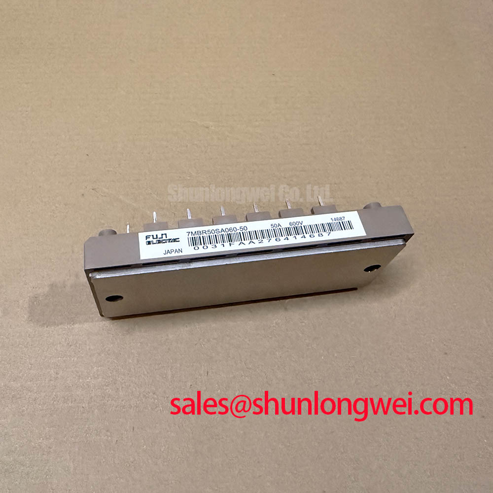

Effective thermal management is fundamental to power module reliability. The inclusion of an on-board NTC thermistor provides a crucial diagnostic function. The integrated NTC thermistor acts like a built-in thermometer for the module’s core. It provides a direct electrical signal corresponding to the baseplate temperature, allowing the control system to prevent overheating, much like a thermostat protects an engine. This allows for precise implementation of thermal shutdown or power derating functions in the system’s control logic, offering a more reliable protective mechanism than external temperature sensors which may exhibit thermal lag.
Optimized Application Scenarios
The specifications of the 7MBR50SA060-50 are well-matched for several key applications:
- AC Motor Drives (VFDs): The 7-in-1 topology provides the inverter and braking functions required for drives up to approximately 15 kW.
- Servo Drives: Its 50A current rating and compact form factor are suitable for driving smaller industrial servo motors that demand precise control.
- HVAC Systems: Efficiently controls compressor and fan motors in commercial air conditioning and refrigeration units.
- General Purpose Inverters: A robust building block for various power conversion tasks, including uninterruptible power supplies (UPS).
This module is an optimal match for applications requiring a complete inverter and brake stage in a space-constrained, cost-sensitive design.
Key Specification Parameters
| Absolute Maximum Ratings (Tc=25°C) | |
|---|---|
| Collector-Emitter Voltage (VCES) | 600V |
| Gate-Emitter Voltage (VGES) | ±20V |
| Collector Current (IC) Continuous | 50A |
| Collector Current (IC) 1ms Pulse | 100A |
| Collector Power Dissipation (Pc) 1 Device | 170W |
| Operating Junction Temperature (Tj) | +150°C |
| Electrical Characteristics – Inverter Part (Tj=25°C) | |
| Collector-Emitter Saturation Voltage (VCE(sat)) | 2.2V (Typ) / 2.7V (Max) at IC=50A |
| Turn-on Time (ton) | 0.35 µs (Typ) |
| Turn-off Time (toff) | 0.50 µs (Typ) |
| Forward Voltage Drop, FWD (VF) | 2.1V (Typ) / 2.6V (Max) at IE=50A |
| Thermal and NTC Characteristics (Tc=25°C) | |
| Thermal Resistance (Rth(j-c)) IGBT | 0.73 °C/W |
| Thermal Resistance (Rth(j-c)) FWD | 1.25 °C/W |
| NTC Resistance (R25) | 5 kΩ ±3% |
| B-Constant (B(25/50)) | 3375 K ±2% |
Engineer’s FAQ
- What is the primary benefit of the ‘7-in-1’ configuration in the 7MBR50SA060-50?
- The 7-in-1 configuration integrates a full three-phase inverter bridge, all necessary freewheeling diodes, and a brake chopper into one module. This significantly reduces the number of components on the BOM, simplifies PCB layout, minimizes assembly labor, and can improve reliability by reducing interconnects.
- How should I calculate the heat sink requirements for this module?
- To size a heat sink, you must first calculate the total power dissipation (conduction and switching losses) based on your specific operating conditions. Then, use the module’s thermal resistance from junction to case (Rth(j-c)), found in the datasheet, along with the thermal resistance of the thermal interface material (TIM). The required heat sink thermal resistance can be determined by the formula: Rth(c-a) = (Tj_max – Ta) / P_total – Rth(j-c) – Rth(TIM).
- What is the function of the integrated NTC thermistor?
- The integrated NTC (Negative Temperature Coefficient) thermistor provides a means for real-time temperature monitoring of the module’s baseplate. Its resistance decreases predictably as temperature increases. This allows the system’s microcontroller to implement over-temperature protection, preventing thermal runaway and enhancing the long-term reliability of the IGBTs.
- What are the recommended gate drive voltage conditions?
- The datasheet specifies the turn-on and turn-off characteristics with a gate voltage of +15V for turn-on and -15V for turn-off. The absolute maximum gate-emitter voltage rating is ±20V. Adhering to the recommended drive voltages ensures optimal switching performance and prevents damage to the gate oxide layer.
Enabling Compact Power Designs
The Fuji 7MBR50SA060-50 provides engineers with a functionally complete power stage for motor control. Its integrated nature allows for the development of compact, efficient, and thermally-aware drive systems with a streamlined design process. This module is a practical solution for balancing performance, space, and system-level reliability.