Fuji 7MBR75SA060: A Technical Review of the 7-in-1 IGBT Power Module
Fuji 7MBR75SA060 IGBT Module | 600V 75A 7-in-1 PIM
Introduction and Core Highlights
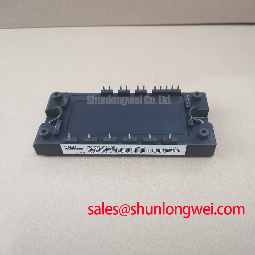
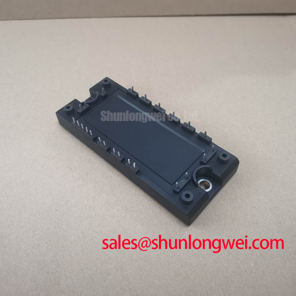
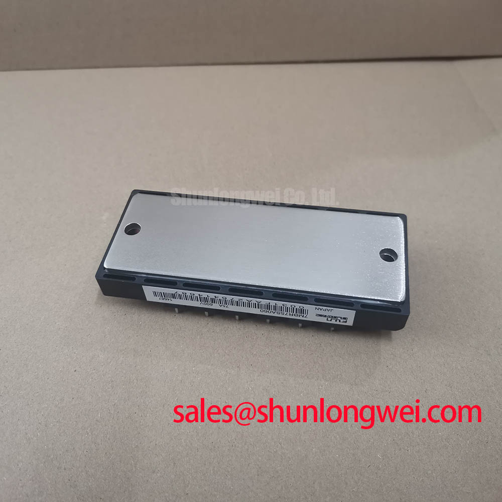
The Fuji Electric 7MBR75SA060 is a highly integrated Power Integrated Module (PIM) that consolidates a complete three-phase drive system into a single, compact package. This module’s primary value is its ability to streamline the design of low-to-medium power motor drives by integrating a three-phase converter, a three-phase inverter, a brake chopper, and protection circuits. This functional density simplifies PCB layout and assembly processes for engineers.
- Core Specifications: 600V | 75A (Inverter) | Integrated NTC Thermistor
- Key Advantages: Reduces component count and assembly time, enables compact power stage design.
For detailed electrical and thermal characteristics, it is recommended to consult the official manufacturer’s documentation.
Download Official Datasheet (Link)
Technical Analysis of the Integrated Design
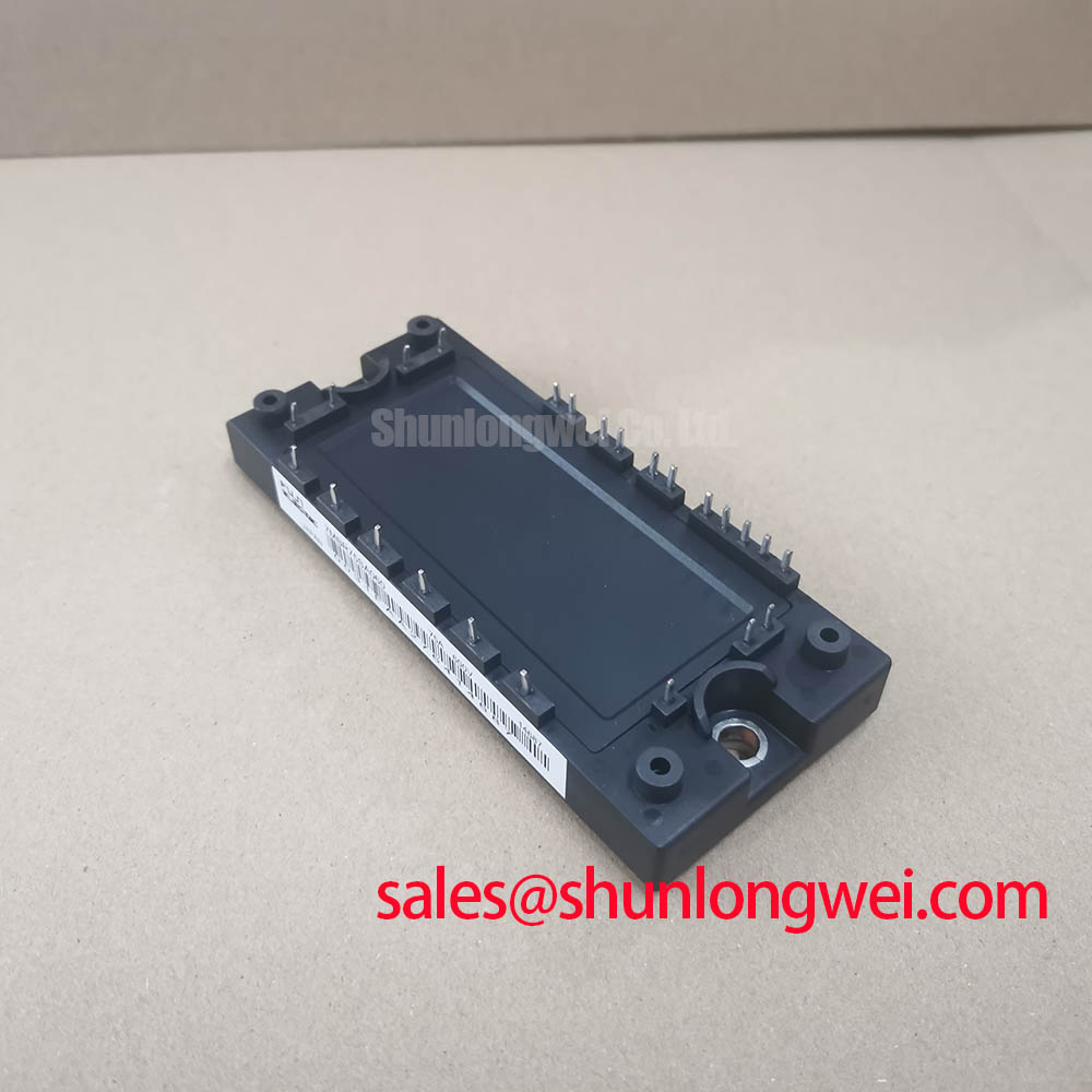
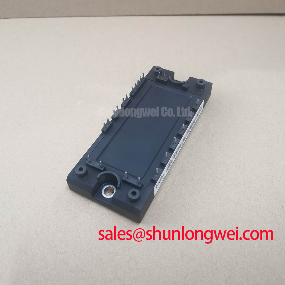
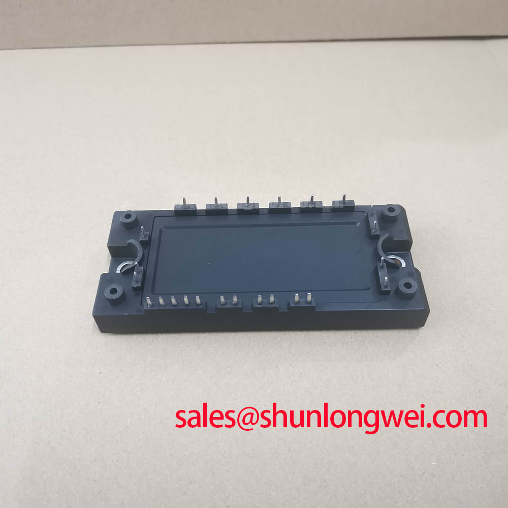
The defining feature of the 7MBR75SA060 is its 7-in-1 integration within a single M-package. This architecture combines the input rectifier bridge, the output inverter stage, and the brake chopper IGBT with its freewheeling diode. For design engineers, this consolidation translates directly into a smaller system footprint and reduced manufacturing complexity. By minimizing external connections and components, the module inherently reduces parasitic inductance, a critical factor in managing EMI and voltage overshoots during high-speed switching operations.
Effective thermal management is fundamental to power module reliability. This PIM includes an integrated NTC thermistor, providing a direct method for monitoring the module’s substrate temperature. This feature allows the control system to implement precise over-temperature protection or dynamic performance adjustments, such as fan speed control. The module’s thermal resistance from junction to case (Rth(j-c)) is a key parameter for heatsink selection. Think of it as the width of a heat escape tunnel; a lower value means heat can be evacuated more efficiently, which is crucial for maintaining junction temperatures within safe operating limits.
Optimized Application Scenarios
The characteristics of the 7MBR75SA060 make it well-suited for several specific applications:
- AC Servo Drives: The module’s compact, all-in-one nature is highly beneficial for space-constrained servo systems where power density is a primary consideration.
- General-Purpose Inverters: For small Variable Frequency Drives (VFDs), this PIM simplifies the power stage design, accelerating time-to-market.
- Uninterruptible Power Supplies (UPS): The integrated converter and inverter sections form the core power topology for many online UPS systems, making this a fitting component choice.
- Industrial Robotics: The module’s integrated braking circuit and compact form factor are advantageous for multi-axis robot arm controllers.
This module is best matched for motor control applications under 15kW requiring a compact, functionally dense power stage solution.
Key Specification Parameters
| Absolute Maximum Ratings (Tc = 25°C) | ||
|---|---|---|
| Parameter | Symbol | Value |
| Collector-Emitter Voltage (Inverter) | VCES | 600V |
| Continuous Collector Current (Inverter) | IC | 75A |
| Total Power Dissipation | PC | 320W |
| Isolation Voltage | Viso | AC 2500V (1 min) |
| Electrical Characteristics (Inverter Part, Tj = 25°C) | ||
| Collector-Emitter Saturation Voltage (Typ.) | VCE(sat) | 2.1V (at IC=75A) |
| Forward Voltage, FWD (Typ.) | VF | 2.0V (at IE=75A) |
Engineer’s FAQ
- How does the integrated NTC thermistor in the 7MBR75SA060 assist with thermal design?
- The built-in NTC thermistor provides a direct, real-time temperature reading of the module’s substrate. This allows an engineer to implement a precise over-temperature protection shutdown in the controller’s firmware. It also enables active thermal management, such as adjusting cooling fan speed based on actual load, optimizing for both acoustics and reliability.
- What are the specified mounting torque requirements for this PIM?
- The datasheet specifies a recommended mounting torque for the terminal and mounting screws (typically M5). Applying the correct torque is critical. Insufficient torque leads to poor thermal contact with the heatsink, while excessive torque can induce mechanical stress on the ceramic substrate, potentially causing cracks and premature failure.
- What is the primary benefit of a 7-in-1 PIM over a discrete component solution?
- The main advantage is system simplification and integration. Using the PIM 7MBR75SA060 significantly reduces PCB layout complexity, component count, and assembly labor. This leads to a smaller end product, lower manufacturing costs, and potentially higher system reliability due to fewer solder joints and interconnections.
- What is the role of the integrated brake chopper?
- The brake chopper is used in motor drive applications to dissipate regenerative energy. When a motor decelerates, it acts as a generator, sending energy back to the DC bus. The brake chopper diverts this energy to an external resistor, preventing the DC bus voltage from rising to a dangerous level and protecting the module and other components.
Design Enablement
The 7MBR75SA060 module provides engineers with a robust, all-in-one component for building compact motor drive systems. Its high level of functional integration and built-in thermal monitoring capability facilitate streamlined design cycles and contribute to reliable end-product performance.