Mitsubishi CM75YE13-12F: A Technical Review and Application Guide
Mitsubishi CM75YE13-12F 600V/75A Single IGBT Module
Introduction and Core Highlights
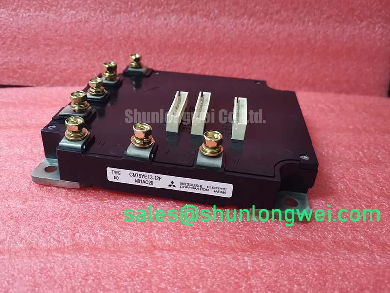
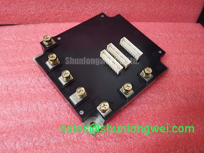
The Mitsubishi CM75YE13-12F is a robust single IGBT module that integrates a power transistor and a free-wheeling diode into a single, electrically isolated package. This design provides engineers with a flexible and reliable component for building custom power stages. It is engineered for straightforward implementation in medium-power industrial applications where dependable switching performance and simplified thermal management are key objectives.
- Core Specifications: 600V | 75A | 2500V Isolation
- Key Advantages: Integrated free-wheeling diode (FWD) supports inductive loads, and the isolated baseplate simplifies assembly and enhances electrical safety.
Download Official Datasheet (PDF)
Technical Analysis for System Design
The engineering value of the CM75YE13-12F lies in its practical integration and thermal design. The module’s 2500Vrms isolation rating between the terminals and the baseplate allows multiple devices to be mounted on a common, non-isolated heatsink. This configuration eliminates the need for separate insulating pads, reducing component count, assembly time, and potential sources of thermal failure. The single-switch topology gives designers the freedom to implement various power converter architectures, from simple buck-boost choppers to more complex, custom inverter legs.
Effective thermal management is fundamental to the reliability of any power system. The thermal resistance from junction to case (Rth(j-c)) for the IGBT is specified at a maximum of 0.32°C/W. Think of thermal resistance as the narrowness of a hallway for heat trying to escape. This module’s low Rth(j-c) value provides a wider hallway, enabling heat to move efficiently from the silicon die to the module case. This characteristic is essential for keeping the device’s junction temperature within its safe operating area, especially under high continuous current loads. A proper thermal design ensures long-term operational stability.
Optimized Application Scenarios
- AC Motor Controllers: The co-packaged free-wheeling diode is critical for safely managing the inductive energy from motor windings during switching, making the module well-suited for variable frequency drives (VFDs).
- Welding Power Supplies: Its ability to handle pulsed currents up to 150A (Icp) makes it a durable choice for the demanding, high-current pulses found in modern welding equipment. This requires robust IGBT protection in welding inverters.
- DC Servo Amplifiers: The defined switching characteristics enable the precise and rapid current control necessary for high-performance servo motor applications.
- General Purpose Inverters and Power Supplies: The 600V/75A rating offers a solid building block for a wide range of DC-AC and DC-DC power conversion tasks where reliability is paramount.
This module is an optimal match for industrial systems needing a robust, individually controlled 600V/75A switch with integrated diode protection.
Key Specification Parameters
| Absolute Maximum Ratings | |
|---|---|
| Collector-Emitter Voltage (Vces) | 600V |
| Gate-Emitter Voltage (Vges) | ±20V |
| Collector Current (Ic) | 75A |
| Collector Power Dissipation (Pc) | 390W (Tc=25°C) |
| Isolation Voltage (Viso) | 2500Vrms (AC, 1 min.) |
| Electrical & Thermal Characteristics | |
| Collector-Emitter Saturation Voltage (Vce(sat)) | 2.7V (Max) at Ic=75A |
| Diode Forward Voltage (VEC) | 2.5V (Max) at Ie=75A |
| Thermal Resistance, IGBT (Rth(j-c)Q) | 0.32°C/W (Max) |
| Thermal Resistance, Diode (Rth(j-c)R) | 0.60°C/W (Max) |
Engineer’s FAQ
- How do I use the datasheet’s thermal resistance values for heatsink selection?
- To select a heatsink, you use the junction-to-case thermal resistance (Rth(j-c)) to calculate the maximum allowable case temperature based on your expected power dissipation and maximum junction temperature (150°C). Then, factor in the case-to-heatsink thermal resistance (Rth(c-f)), which is typically around 0.05°C/W with thermal grease. Your chosen heatsink’s thermal resistance to ambient (Rth(f-a)) must be low enough to keep the module’s case within its calculated temperature limits.
- What are the mounting torque recommendations for the CM75YE13-12F?
- The datasheet specifies a recommended screwing torque for both the M5 main terminals and the M5 mounting holes. For reliable electrical and thermal contact, a torque of 1.7 to 2.1 N·m should be applied.
- What is the role of the integrated free-wheeling diode (FWD)?
- The FWD is the IGBT’s silent partner in applications with inductive loads like motors. When the IGBT turns off, the energy stored in the inductor needs a path to flow. The FWD provides this path, preventing a large and potentially damaging voltage spike from occurring across the IGBT’s collector and emitter.
- What is the absolute maximum gate-emitter voltage?
- The absolute maximum rating for the gate-emitter voltage (VGES) is ±20V. Applying a voltage outside this range, even briefly, can cause permanent damage to the sensitive gate oxide layer, leading to device failure.
Enabling Robust Power Designs
The CM75YE13-12F offers a proven, no-frills solution for designers who require a reliable, isolated power switch. Its straightforward integration, robust electrical ratings, and flexible single-switch configuration empower engineers to develop durable and efficient medium-power conversion systems with simplified thermal and mechanical design.