Mitsubishi PM30CNA060 IPM: A Technical Review for Reliable Motor Control
## PM30CNA060: Mitsubishi 600V/30A C-Series IPM
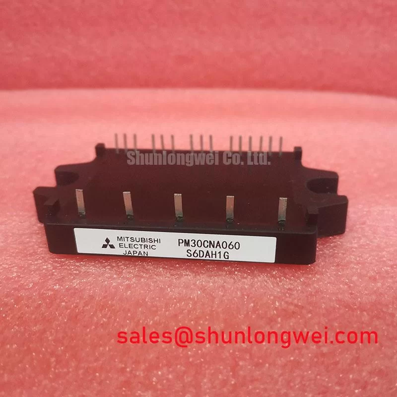
The Mitsubishi PM30CNA060 is a highly integrated Intelligent Power Module (IPM) that consolidates a three-phase IGBT inverter bridge, gate drive circuits, and comprehensive protection functions into a single compact package. This integration provides a robust solution for simplifying the design of variable frequency drives and other motor control systems. By incorporating essential components, this module significantly reduces component count and enhances overall system reliability.
* **Core Specifications**: 600V | 30A | Three-Phase Inverter
* **Key Advantages**: Integrated protection for enhanced reliability, simplified PCB layout, and reduced design time.
* **Design Simplification**: The module includes built-in HVICs, bootstrap diodes, and an NTC thermistor, minimizing the need for external components for gate drive and temperature sensing.
Download Official Datasheet (PDF)
Technical Analysis for System Integration
The primary value of the PM30CNA060 lies in its high level of integration. As an Intelligent Power Module, it contains not only the six IGBTs and six freewheeling diodes required for a three-phase inverter but also the high-voltage and low-voltage ICs needed to drive them. This eliminates the complexity of designing, sourcing, and qualifying separate gate drivers, bootstrap circuits, and protection logic, directly contributing to a faster time-to-market and a more compact design.
A standout feature is the comprehensive suite of built-in protection mechanisms. The module provides short-circuit (SC) protection, over-temperature (OT) protection via an integrated NTC thermistor, and control supply under-voltage (UV) lockout. Think of these protections as a built-in safety system for the power stage; it’s like having a dedicated supervisor for each IGBT that can instantly shut it down during a fault condition without waiting for the main system controller to react. This self-contained protection is crucial for preventing catastrophic failures in demanding applications.

Effective thermal management is another key aspect addressed by this module’s design. The module’s thermal resistance, Rth(j-c), is specified per IGBT, allowing for precise heatsink calculations. This value can be imagined as the width of a pipe for heat to escape; a lower thermal resistance means a wider pipe, allowing heat to flow away from the IGBT junction more easily. The integrated NTC thermistor provides real-time temperature data, enabling the system controller to implement advanced thermal monitoring and overload protection.
Optimized Application Scenarios
The PM30CNA060 is well-suited for a range of low to medium-power motor control applications where reliability and a compact footprint are critical.
* **AC Servo Drives and Small Industrial Inverters:** The 30A rating and integrated protection make it ideal for driving AC motors in automation equipment, where high reliability and compact size are essential.
* **HVAC Systems:** In variable-speed compressors and fans for air conditioning units, the module’s integration simplifies the power stage, contributing to energy-efficient and quiet operation.
* **Appliance Motor Control:** Suitable for advanced washing machines, pumps, and fans, where the all-in-one design reduces manufacturing complexity and enhances long-term durability.
* **General Purpose Low Power Inverters:** Its straightforward interface and robust protection are beneficial for any application requiring the conversion of DC to three-phase AC power up to approximately 7.5 kW.
For low-power motor drives requiring a compact, protected, and easy-to-implement inverter stage, this IPM presents an excellent engineering choice.
Key Specifications of the PM30CNA060
| Parameter | Value |
|---|---|
| Absolute Maximum Ratings (Tj=25°C unless otherwise noted) | |
| Collector-Emitter Voltage (V_CES) | 600V |
| Collector Current (DC) (I_C) | 30A |
| Collector Current (Peak) (I_CP) | 60A (1ms) |
| Collector Power Dissipation (P_C) | 89.3W (per IGBT) |
| Electrical Characteristics (Tj=25°C) | |
| Collector-Emitter Saturation Voltage (V_CE(sat)) | 2.2V (typ) / 2.7V (max) at Ic=30A |
| Diode Forward Voltage (V_F) | 2.2V (typ) / 2.7V (max) at Ie=30A |
| Control and Protection | |
| Control Supply Voltage (V_CC) | 15V (13.5V to 16.5V) |
| Isolation Voltage (V_isol) | 2500 Vrms (1 minute) |
| Short Circuit Protection Trip Level (I_SC) | 48A (typ) |
Engineer’s FAQ for PM30CNA060
1. What are the primary advantages of using the PM30CNA060 IPM over a discrete solution?
The main advantage is integration. The PM30CNA060 combines IGBTs, freewheeling diodes, gate drivers, and protection circuits in one tested package. This simplifies PCB layout, reduces assembly time, and improves system reliability by minimizing external component count and potential points of failure. It also ensures optimized switching performance as the driver is matched to the IGBTs.
2. How do I use the built-in over-temperature protection?
The module contains an NTC (Negative Temperature Coefficient) thermistor. You can connect this thermistor to your microcontroller’s ADC via a simple voltage divider circuit. The datasheet provides the R-T (Resistance-Temperature) curve, allowing you to convert the measured resistance or voltage into a temperature reading. You can then set a software-defined temperature limit to trigger a shutdown or warning.
3. What are the recommended power supply decoupling practices for the control circuits?
Each of the three low-side control supplies (VNC) and the single high-side supply (VPC) should have a high-quality, low-ESR ceramic bypass capacitor (typically 0.1µF to 1.0µF) placed as close as possible to the module’s power and ground pins. This is critical for filtering noise and ensuring stable operation of the internal drive and protection logic, especially during high-speed switching events.
4. The module has a fault output pin (Fo). How does it operate?
The Fo pin is an open-collector output that signals a fault condition (Short-Circuit, Control Under-Voltage). In normal operation, this pin is high-impedance. When a fault occurs, an internal transistor pulls this pin low. You should connect it to your microcontroller’s interrupt pin with a pull-up resistor (e.g., 5kΩ to 10kΩ) to Vcc. This allows for an immediate, hardware-level response to system faults.
This C-Series IPM offers a streamlined path to developing reliable and compact motor control systems. By integrating the power stage with critical drive and protection functions, the PM30CNA060 enables engineers to focus on system-level performance rather than the complexities of discrete power component design.