P546A2804 Vinco 1200V 15A flowPIM 0 IGBT Module: Technical Overview and Applications
P546A2804 Vinco 1200V 15A flowPIM 0 IGBT Module
Introduction and Core Product Highlights
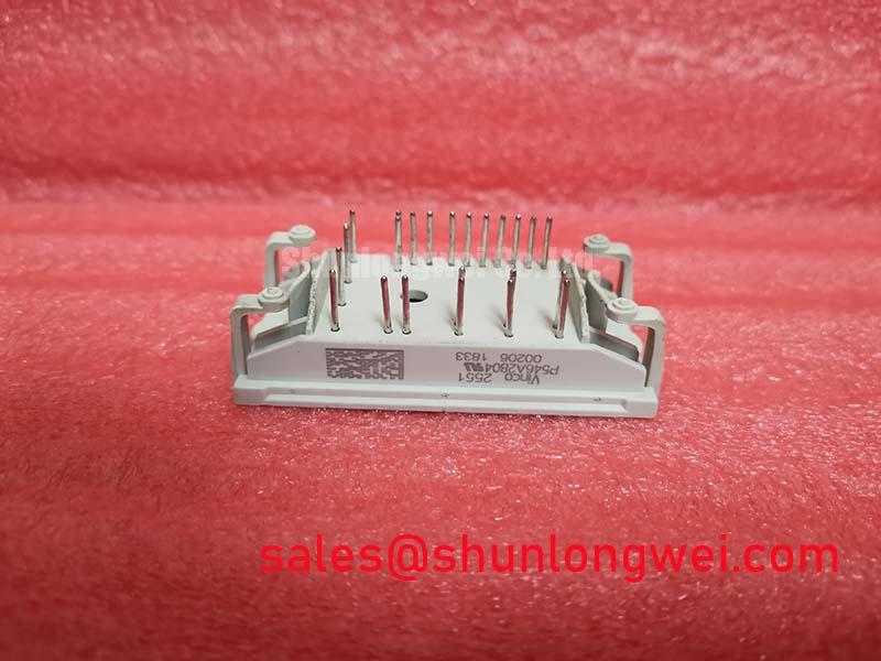
The P546A2804 Vinco is an integrated power module that streamlines three-phase industrial motor drive designs. It consolidates an input rectifier, a three-phase inverter, a brake chopper, and an NTC temperature sensor into a single compact housing. This high-density integration minimizes external wiring while offering robust thermal and electrical performance.
- Core Technical Specifications: 1200V Block Voltage | 15A Continuous Collector Current | flowPIM 0 Package housing.
- Key Engineering Advantages: Significantly reduced board footprint and lower parasitic loop inductance for cleaner gate-switching transitions.
How do design engineers accurately calculate power dissipation under variable loads? This module simplifies safety monitoring by offering integrated temperature sensing alongside highly efficient switching silicon.
Download technical documentation and product specifications
Technical Analysis and Engineering Value
Moving from discrete layouts to a unified Power Integrated Module (PIM) topology directly addresses trace layout complexity. The internal structure of the P546A2804 Vinco is optimized to keep commutation paths extremely short. This physical proximity limits the internal parasitic inductance, suppressing transient overvoltage spikes during fast turn-off cycles.
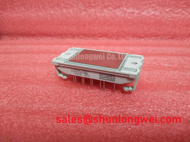
The thermal architecture relies on a direct copper bonded (DCB) ceramic substrate. This provides electrical isolation while offering a highly conductive path to the external cooling assembly. Think of thermal resistance as a highway lane restriction; lower values allow heat “traffic” to flow away from the silicon junctions with minimal delay, keeping the device well within its safe operating boundaries.
Furthermore, safety is improved by the integrated NTC thermistor. Positioned close to the switching chips, the sensor yields accurate temperature feedback. This tight coupling lets gate driver controllers respond to thermal fluctuations before thermal overload can degrade the internal wire bonds.
Optimized Application Scenarios
- Industrial Motor Drives (VFDs): Consolidates the complete inverter stage with a brake chopper, making it ideal for variable frequency drives.
- Solar Inverters: High voltage blocking voltage and low switching losses enable efficient DC-to-AC power conversion in grid-tied systems.
- Uninterruptible Power Supplies (UPS): Rapid switching capabilities ensure consistent backup power supply with minimal harmonic distortion.
- Industrial Pumps and Fans: Compact packaging reduces overall enclosure dimensions in localized flow-control systems.
The P546A2804 Vinco is best suited for space-constrained industrial drive designs requiring a 1200V rating and integrated thermal safety features.
Key Specifications Table
| Parameter Group | Specification Parameter | Value | Unit / Conditions |
|---|---|---|---|
| Absolute Maximums | Collector-Emitter Voltage (Vces) | 1200 | V (Tj = 25°C) |
| Continuous DC Collector Current (Ic) | 15 | A (Tc = 80°C) | |
| Isolation Voltage (Visol) | 2500 | V (AC, 1 minute) | |
| Electrical (Inverter) | Collector-Emitter Saturation Voltage | 2.1 | V (Typical, Tj = 25°C, Ic = 10A) |
| Gate-Emitter Threshold Voltage (Vge) | 5.8 | V (Range: 5.0V to 6.5V) | |
| Thermal & NTC | Thermal Resistance (Rth_j-c, per IGBT) | 1.45 | K/W |
| NTC Rated Resistance | 22 | kΩ (at T = 25°C) |
Engineers FAQ
Q1: What are the main benefits of the integrated NTC in the P546A2804 Vinco module?
A1: The internal NTC is placed on the substrate close to the IGBTs. This close physical proximity minimizes temperature tracking delays, allowing system controllers to accurately monitor the silicon thermal state and trigger overtemperature shut-down routines.
Q2: How does the flowPIM package reduce voltage overshoots during switching?
A2: The package optimizes the internal routing between the rectifier and the inverter. Lowering the loop physical area directly limits stray inductance, which significantly curtails voltage overshoots when turning off under high current loads.
Q3: What mounting practices are critical to preserve the module’s thermal path?
A3: Ensure a uniform thermal paste layer of 50 to 100 micrometers is applied to the baseplate. Screws must be torqued progressively in an alternating sequence to prevent baseplate tilt or substrate damage.
Closing Statement
The P546A2804 Vinco power module represents a balanced, pre-assembled solution for modern inverter designs. By combining essential power stages and thermal sensors in a standardized flowPIM 0 footprint, it eliminates trace layout bottlenecks and enhances thermal dissipation. This layout simplicity empowers hardware designers to create compact power electronics platforms with fewer passive components.