PM400DVA060-4: A Technical Guide to the 400A Intelligent Power Module
## PM400DVA060-4 600V 400A Intelligent Power Module
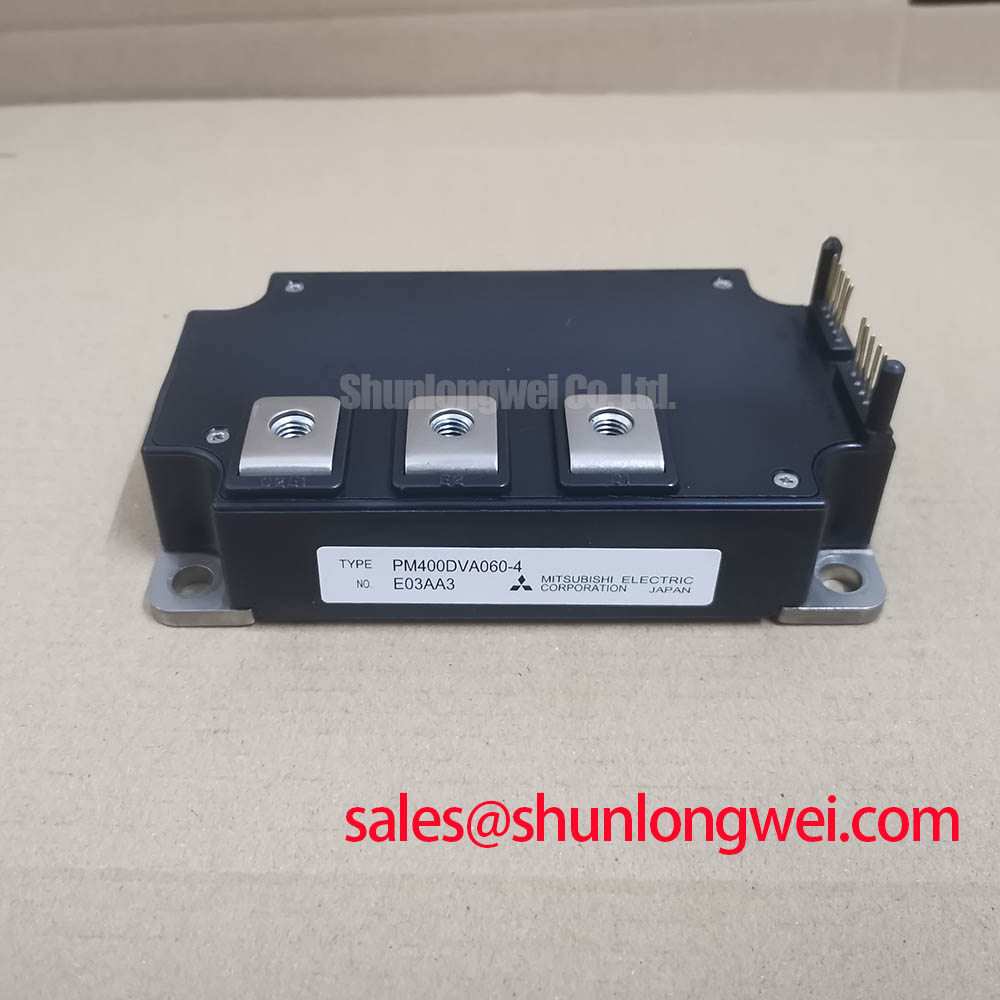
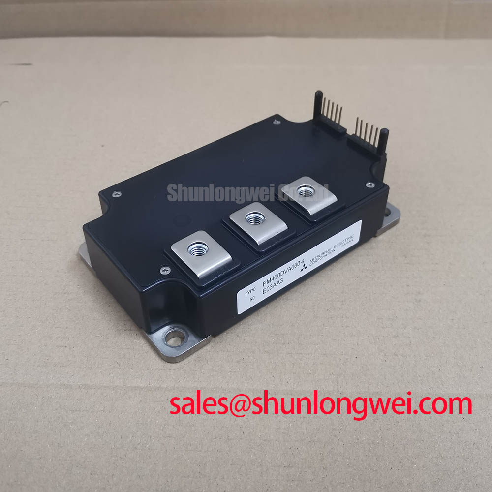
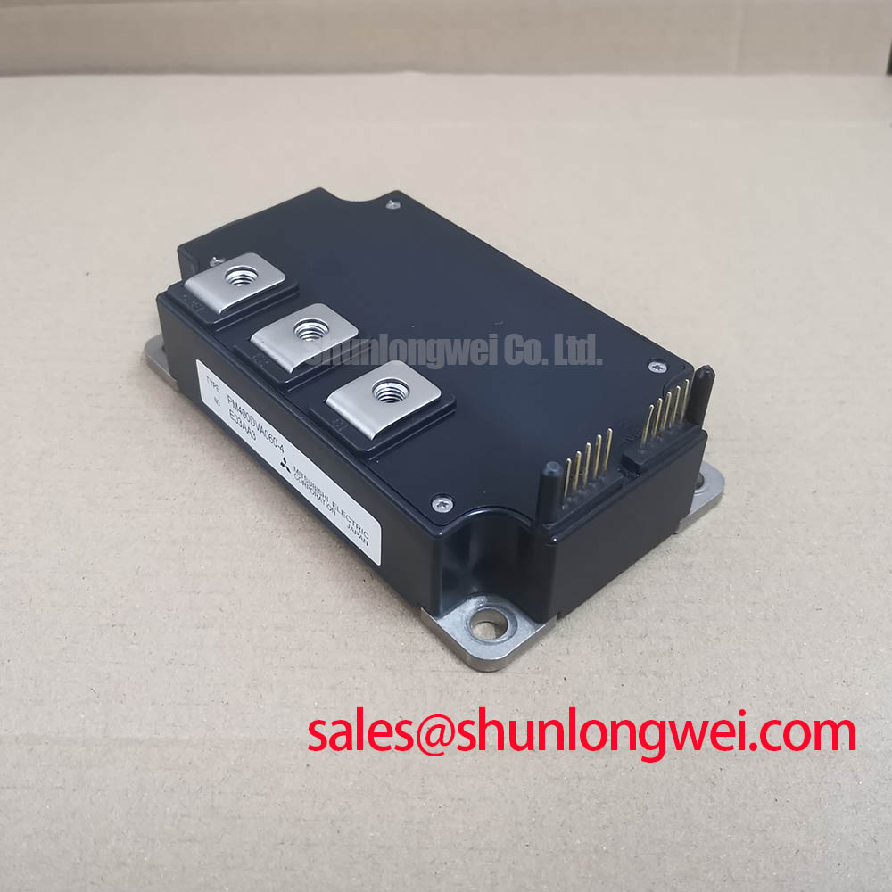
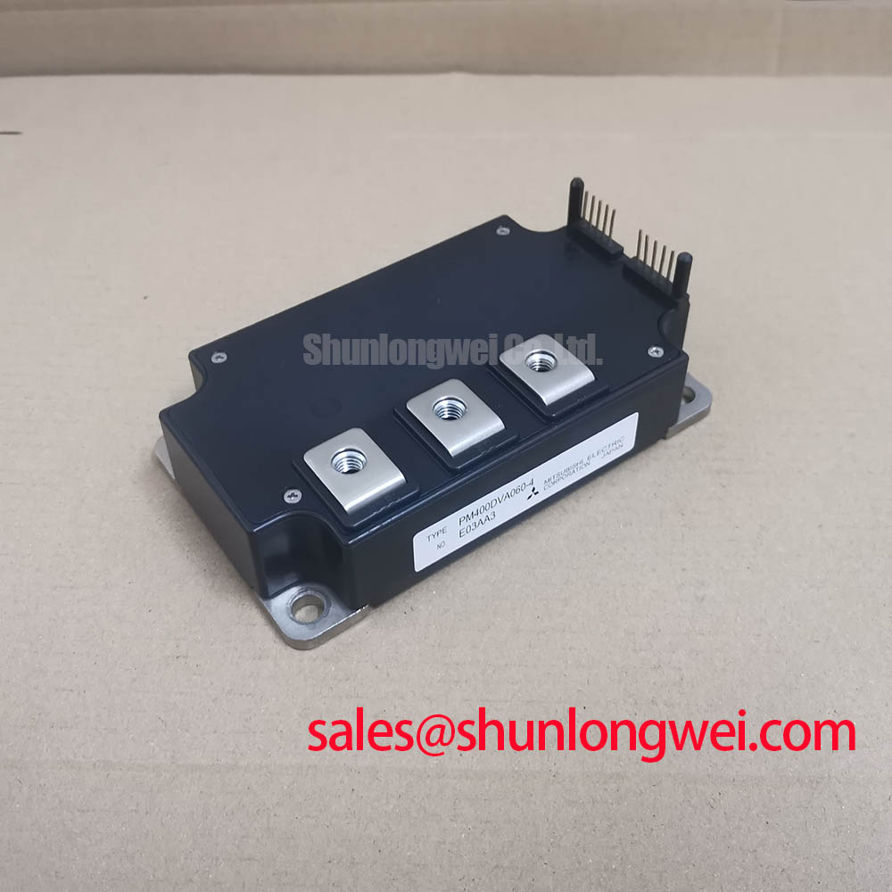
The Mitsubishi PM400DVA060-4 is a dual intelligent power module (IPM) that integrates a high-current 600V/400A IGBT stage with dedicated gate drive and protection circuits. This integration provides a robust power switching solution for high-frequency applications, featuring built-in safeguards against short-circuit, over-temperature, and under-voltage events. By combining these functions into a single component, the module simplifies complex power system designs and enhances operational reliability.
* **Core Specifications**: 600V | 400A | VCE(sat) 2.35V (typ)
* **Key Advantages**: Integrated protection logic, optimized gate drive circuitry.
* **Design Benefit**: Reduces the need for external protection components, simplifying the overall system layout and improving reliability under fault conditions.
Download Official Datasheet (PDF)
Technical Analysis for System Integration
The primary value of the PM400DVA060-4 lies in its integrated protection and control systems. The module contains dedicated circuits that actively monitor for short-circuit (SC), over-temperature (OT), and supply under-voltage (UV) conditions. Upon detecting a fault, the internal logic safely shuts down the IGBTs and issues a fault signal (Fo) to the system controller. This autonomous protection capability significantly reduces the burden on external control hardware, leading to a more streamlined and fault-tolerant design.
Effective thermal management is critical for high-power modules. The PM400DVA060-4 specifies a junction-to-case thermal resistance (Rth(j-c)) of 0.11°C/W for the IGBT part. This value is analogous to the width of a pipe for heat flow; a lower number indicates a wider pipe, allowing heat to escape more efficiently from the semiconductor junction to the heatsink. This efficient heat transfer is essential for maintaining the junction temperature within its safe operating area, especially under the high current loads this module is rated for.
Optimized Application Scenarios
The characteristics of the PM400DVA060-4 make it a strong candidate for several demanding power conversion applications:
* **Industrial Motor Drives**: The 400A continuous current rating and integrated short-circuit protection provide the necessary robustness for driving large AC induction or permanent magnet motors.
* **Uninterruptible Power Supplies (UPS)**: High reliability is paramount in UPS systems. The module’s built-in over-temperature and under-voltage protection helps ensure continuous, stable operation.
* **Servo Drives**: The module’s specified switching times, with a typical turn-on time (ton) of 1.4µs and turn-off time (toff) of 2.0µs, are suitable for the dynamic control required in high-performance motion control systems.
* **Welding Power Supplies**: The high peak current capability (Icp up to 800A) and inherent ruggedness can handle the pulsed power demands of welding applications.
This module is best matched for applications requiring robust, integrated power switching up to 400A with minimal external protection circuitry.
Key Specifications of the PM400DVA060-4
| Parameter | Symbol | Conditions | Value | Unit |
|---|---|---|---|---|
| Absolute Maximum Ratings (Tj=25°C) | ||||
| Collector-Emitter Voltage | VCES | VD = 15V, VCIN = 5V | 600 | V |
| Collector Current | IC | TC = 25°C | 400 | A |
| Peak Collector Current | ICP | TC = 25°C | 800 | A |
| Collector Dissipation | PC | TC = 25°C | 1136 | W |
| Isolation Voltage | Viso | AC 1 min. | 2500 | Vrms |
| Electrical Characteristics (Tj=25°C unless noted) | ||||
| Collector-Emitter Saturation Voltage | VCE(sat) | IC = 400A, Tj=125°C | 2.55 (typ) / 3.05 (max) | V |
| FWDi Forward Voltage | VEC | -IC = 400A | 2.20 (typ) / 3.30 (max) | V |
| Protection & Control Characteristics | ||||
| Short Circuit Trip Level | SC | Tj = 125°C, VD = 15V | 910 (typ) | A |
| Over Temperature Trip Level | OT | VD = 15V | 110 (typ) | °C |
| Under Voltage Trip Level | UV | 12.0 (typ) | V | |
Note: These parameters are sourced from the official datasheet. Engineers should consult the complete document for detailed graphs, test conditions, and application notes.
Engineer’s FAQ
What is the primary benefit of using an IPM like the PM400DVA060-4 over a discrete IGBT and driver solution?
The main advantage is system integration and reliability. The PM400DVA060-4 combines the power IGBTs, freewheeling diodes, and an optimized gate driver with protection logic in a single, factory-tested module. This eliminates potential design issues related to gate drive layout, parasitic inductance, and component selection, while the integrated short-circuit and thermal protection provides a more robust and reliable solution than typically achieved with discrete components.
How should the heatsink requirements be determined for this module?
Heatsink calculation requires determining the total power dissipation (conduction and switching losses) under worst-case operating conditions. The required thermal resistance of the heatsink can then be calculated using the formula: Rth(c-a) = (Tj(max) – Ta) / P_total – Rth(j-c) – Rth(c-s), where Tj(max) is the maximum junction temperature (150°C), Ta is the ambient temperature, P_total is total power loss, Rth(j-c) is the module’s junction-to-case thermal resistance (0.11°C/W for the IGBT), and Rth(c-s) is the thermal resistance of the interface material.
What is the function of the ‘Fo’ (Fault Output) pin?
The Fo pin is an open-collector output that signals a fault condition. It transitions to a low state when any of the internal protection circuits (short-circuit, over-temperature, or under-voltage) are triggered. This signal should be monitored by the host microcontroller to initiate a system shutdown or alert, with a minimum pulse width of 1.0ms.
What are the recommended mounting torque specifications?
According to the datasheet, the M6 mounting screws should be tightened to a torque of 3.92 to 5.88 N·m. The M6 main terminal screws have the same specification. Adhering to these values is crucial for ensuring proper thermal contact and reliable electrical connections.
This Intelligent Power Module provides a highly integrated foundation for developing efficient and durable high-power inverter and motor control systems. Its built-in protection logic allows engineering teams to focus on system-level performance while ensuring the power stage remains secure.