PM75CLS120: An Integrated Power Solution for High-Reliability Motor Drives
## PM75CLS120: Mitsubishi 1200V 75A CIB Intelligent Power Module
The Mitsubishi PM75CLS120 is an L1-Series Intelligent Power Module (IPM) that delivers a complete power conversion solution in a single component. It integrates a three-phase converter, a three-phase inverter, and a brake chopper (CIB), providing a functionally dense foundation for high-reliability motor control systems. The module leverages Mitsubishi’s Carrier Stored Trench-gate Bipolar Transistor (CSTBT™) technology to achieve an optimal balance between conduction losses and switching performance.
* **Core Specifications:** 1200V | 75A | CIB (Converter-Inverter-Brake) Topology
* **Key Advantages:** Simplifies system layout by reducing component count and enhances operational safety with integrated protection circuits. This integration helps accelerate the design cycle for robust power semiconductors applications.
* **Design Benefit:** The built-in brake chopper circuit provides a ready-made solution for managing regenerative energy, a common requirement in dynamic motor applications.
For full specifications, including characteristic curves and thermal design criteria, refer to the official manufacturer documentation for the L1-Series IPMs. While a direct datasheet for the PM75CLS120 is not publicly available, the PM75CL1B120 datasheet provides representative technical data for this series.
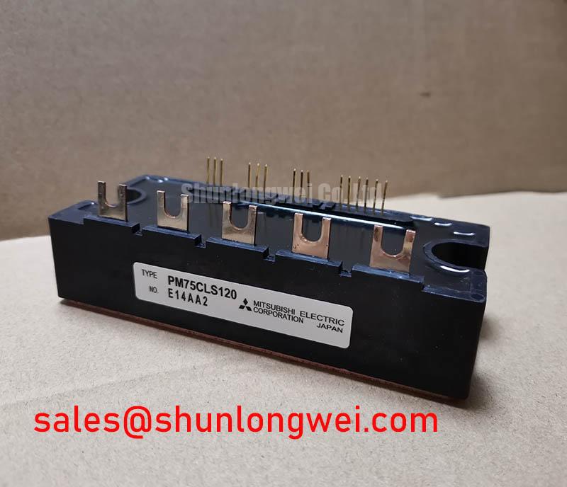

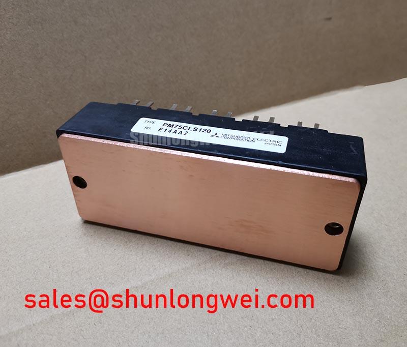
Technical Analysis: Integration and Efficiency
The core value of the PM75CLS120 lies in its high level of integration. By combining the AC-to-DC converter, DC-to-AC inverter, and braking IGBT into one package, it eliminates complex busbar connections between separate modules. This reduces overall system size and, more importantly, minimizes stray inductance. Lower inductance contributes to reduced voltage overshoots during switching, which improves reliability and lowers electromagnetic interference (EMI). The integrated gate drive and protection logic—including short-circuit, over-temperature, and under-voltage lockout—provide a pre-validated safety net that simplifies the control interface design.
A key performance parameter is the collector-emitter saturation voltage (VCE(sat)), specified at a typical value of 1.75V for the inverter part. This is achieved through the use of CSTBT™ technology. You can think of VCE(sat) as the “toll” the current pays to pass through the switch when it’s on. A lower VCE(sat) means less energy is wasted as heat (lower conduction losses), leading to higher overall efficiency. This allows for a smaller heatsink, saving space and cost, a concept further explored in guides to IGBT thermal design.
### Optimized Application Scenarios
The specific feature set of the PM75CLS120 makes it well-suited for several demanding applications:
* **AC Servo Drives:** The integrated brake circuit is essential for dissipating regenerative energy during rapid deceleration, ensuring precise position control in robotics and CNC machines.
* **Variable Frequency Drives (VFDs):** Its CIB topology provides a complete power stage for compact motor drives used in pumps, fans, and conveyor systems, where reliability and efficiency are primary concerns.
* **General Purpose Inverters:** The module’s robust construction and comprehensive protection simplify the design of versatile inverters for a wide range of industrial machinery.
* **Uninterruptible Power Supplies (UPS):** The high integration level enables the creation of power-dense online UPS systems, where the CIB module can manage the entire AC-DC-AC conversion path.
This module is an optimal choice for motor control systems where a compact, all-in-one power stage is required to enhance reliability and simplify manufacturing.
### Key Specification Parameters
The following values are based on official documentation for the Mitsubishi L1-Series 1200V/75A IPMs.
| Absolute Maximum Ratings (Tj = 25°C) | ||
|---|---|---|
| Parameter | Symbol | Value |
| Collector-Emitter Voltage | VCES | 1200 V |
| Collector Current (Inverter) | ±IC | 75 A |
| Collector Current (Brake) | IC | 35 A |
| Collector Power Dissipation (Inverter) | PC | 480 W |
| Isolation Voltage | Viso | 2500 Vrms (1 min) |
| Electrical Characteristics (Inverter Part, Tj = 25°C) | ||
| Collector-Emitter Saturation Voltage (IC = 75A) | VCE(sat) | 1.75 V (Typ.) |
| Short Circuit Withstand Time | tsc | > 10 µs |
### Engineer FAQ
The Converter-Inverter-Brake (CIB) topology integrates the three main power stages of a motor drive into one module. This reduces the physical footprint, simplifies the assembly process, and lowers the parasitic inductance in the DC bus link, which is a key aspect of the IPM advantage for reliable power switching.
Effective thermal management requires ensuring a low thermal resistance path from the module’s baseplate to the heatsink. Use an appropriate thermal interface material and apply the specified mounting torque (typically 3.5 – 4.5 N·m for this package type) to the mounting screws to minimize contact thermal resistance. The integrated NTC thermistor should be connected to a monitoring circuit to enable over-temperature protection or performance throttling.
The module contains dedicated current-sensing emitters on the IGBTs. If the current exceeds a predefined threshold, the internal gate drive logic detects the fault and initiates a soft shutdown of the affected IGBT. It then sends a fault signal (FO) to the system controller. This prevents catastrophic failure during a short-circuit event.
The PM75CLS120 offers a robust, verified power stage that allows engineering teams to bypass the complexities of discrete component selection, gate drive design, and protection circuit implementation. This approach enables a focus on application-level software and control, accelerating the development of efficient and reliable industrial drive systems.