Proper sequencing of the multiple power rails in a system is a critical function and can be accomplished using different approaches.
Experienced designers know that one of the riskiest periods in a product’s operating cycle is when power is turned on. This power-up phase is when each of the multiple power rails must come up to its nominal value in the right order, within a designated time window, and without transients, ringing, or overshooting.
If the sequencing is not correct, in the best case, the system will not “boot up” properly, or its performance will be erratic (and yet may work just fine on a retry); in the worst case, some components will damage, which is especially a risk with power devices. Note that power-down may have similar timing mandates, with the risk of damage – until the next time the unit is powered up, of course, and the unit no longer works where it previously did.
A high-performance IC such as an FPGA may have half a dozen or more distinct DC power rails to support the device core, RAM, internal buffers, and external I/O such as I2C, SPI, LVDS, and other ports. These rails may have different but closely spaced nominal values such as 1.2 V, 1.5 V, and 1.7 V, or several of these rails may have the same nominal value but with different tolerances or physical locations. Similarly, a highly integrated, application-specific IC such as a Wi-Fi network node may have multiple rails to support internal functions as well as interface voltages required by an industry standard or a bipolar supply for the antenna driver and its power amplifier.
The power-rail count doesn’t end with that single IC. The number of such rails will often increase further with the complete system, which may have motor drivers, power MOSFETs/IGBTs, or special communications interfaces such as Ethernet or even legacy RS-232/422 ports. As a result, regardless of physical size, the complete system may have ten or more rails sourced by independent DC regulators (also called power converters).
The designer’s challenge is to ensure that when primary power is applied – whether via a discrete on-off switch or a soft-switch equivalent — these rails power up to their full, final value in a carefully choreographed sequence (Figure 1).

Even if there is no permanent damage, operational malfunctions may be an unacceptable consequence of incorrect sequencing: consider the effect of turning on the motor-power MOSFETs before the motor-control software is initialized and ready to control those MOSFETs. Nor do these problems have to be associated with a formal power-up event; instead, they can be due to the insertion of circuit cards in “hot swap” designs.
To deal with these issues, specialized power-management ICs (PMICs) are available which implement power sequencing and timing. A full-function PMIC allows the design engineer to:
- establish turn-on/off sequencing across multiple rails with respect to each other.
- control the ramp up/down rates of each rail, if needed.
- manage the various rails if any single rail fails.
Generally, the timing between rails is determined by rail voltages rather than absolute time values and lags, and the time period between the successive rails being “turned on” is on the order of milliseconds. The interrelationship guidelines range from simple, such as “turn supply B rail on only when supply A rail is on,” or more complicated, such as “turn supply C rail on only when both A and B rails are at final voltage.” Note that “on” is defined by the application requirements and is most often 90% of the final rail voltage, but in critical applications, it may be reached within five or even 2% of the final voltage.
Even though in most designs it is the voltage that is critical, not the time itself, some designs substitute timing as the criteria instead. This is possible if the designer knows that a specific voltage rail takes a well-defined time to reach the desired value, and timing is much easier to measure accurately than voltage.
In these cases, a rule such as “turn on supply A rail once supply B is on” is translated into “turn B’s rail on 50 milliseconds after A’s rail is turned on.” However, this approach has to be used with caution since there is no verification that supply A’s rail has actually come up to the desired value, other than “it’s supposed to be OK-enough at this time.”
Some PMICs integrate both the DC/DC regulators (LDO and switching) plus the requisite sequencing. They are optimized for a target application such as notebook PCs (CPU, memory, display, I/O, and other standard functions). While these are obviously well suited to the intended application and should be considered in that context, they also inherently limit the overall flexibility in the designer’s choice of voltage rails and types for other applications.
The requirement to sequence power supplies is not new. For example, for vacuum tubes – now made largely obsolete by ICs except for specialized applications such as X-ray machines or radio/TV broadcast transmitters – it is a common requirement. The tube’s filament may have to be turned on and at the final operating temperature before the tube’s plate can be energized by its “B+” voltage. This time delay ranges from zero for legendary consumer five-tube AM radio of the 1940s and 1950s, to many minutes for tubes used in kW-range broadcast transmitters.
The sequence is sometimes implemented manually by the system operator via on/off switches; in other cases, a special electromechanical relay with a built-in timer is used. Certainly, neither a manual control nor a relay-based solution is practical or desirable for most of today’s products, especially those targeting mass markets and average consumers.
Start at the physical layer
In any discussion of power sequencing, there are two aspects to keep in mind: the control signal coming from the sequencer and the corresponding control input at each DC regulator.


Obviously, the sequencer must have enough control outputs and, in some cases, also have some provision for expansion of the number if needed. These outputs are simple, logic-level control signals.
The complementary DC regulators that they are enabling must either have a single pin enable (EN) input, or the user must add an electronic switch (usually a MOSFET) between the regulator output and the physical power rail it drives, and then control this switch (Figure 2).
It is generally preferable to choose a DC regulator that has a simple, logic-level Enable control, if available, or select PMIC, which can directly drive the discrete power rail on/off MOSFET with suitable current/voltage ratings and does not need a separate MOSFET driver.
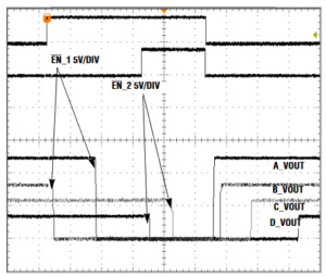
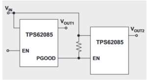
In the simplest case of sequential sequencing, where each rail is turned on in series as another rail becomes “good,” the solution is often simple. If each preceding rail’s regulator has a “power good” (PG) output and the next regulator has an Enable control input, the PG indicator is connected to the EN input. When the first regulator signals PG, it automatically turns on the next one, and so on down the line as a sort of “daisy chain” ripple effect (Figure 3).

This approach will work for any number of DC regulators in series, but that virtue is also its limit: they must have a sequential pattern (although one PG can be connected to more than one EN), and there is little flexibility. Also, this approach cannot control timing when one supply must wait a specified interval of time before turning on, and it cannot address turn-off sequencing, which may be as important as turn-on.
To overcome some of these issues, a reset IC with timer control can be used for power-up sequencing. The venerable and versatile 555 timer IC (or newer variant) can be used to control sequencing by invoking a time period after the first rail reaches the nominal window value or after a rail shuts down. The time period is set in hardware by the user using resistors with the 555, so it is established by design and BOM, not firmware (Figure 4). While this may not appear to be an elegant approach, it is an effective one, especially useful when a sequencing problem becomes visible only after the design is done and prototype boards are being evaluated (yes, that happens).


For systems with more rails and needing more flexibility, a PMIC such as the MAX16029 from Analog Devices/Maxim Integrated can be used for four channels, with the time-delay period user-programmed via capacitors, thus avoiding memory volatility or start-up issues (Figure 5).


Each of the four channels is independent of the others, and each channel’s output can be used in an open-drain configuration that supports rail voltages up to 28 V, needed for higher-range DC regulators. Other PMICs with this functionality have their timing set via a PMBus interface rather than capacitors or resistors, and so can be daisy-chained to handle more than four rails.
The next part of this article looks at higher-end sequencing solutions and their attributes.
Related EE World Content
If you’re designing power ICs, here are some tools to consider|
Selecting and applying programmable power supplies
Device Enables Fault-Proof Sequencing Of FPGA Power Rails
Supervisory ICs tame power-up glitch headaches, Part 1
Supervisory ICs tame power-up glitch headaches, Part 2
External References
Texas Instruments, “Power-supply sequencing for FPGAs”
Analog Devices, “Power Supply Sequencing Simplified”
Analog Devices, “Complex Power-Supply Sequencing Made Easy
Advanced Micro Devices, Inc., “Simplified Power Sequencing”
Microchip Technology, Inc., “Why Is Power Sequencing Needed?”