Technical Analysis of the Mitsubishi PM15CKF120 CIB Power Module
Mitsubishi PM15CKF120 CIB Module | 1200V 15A
Technical Overview of the Integrated Power Stage
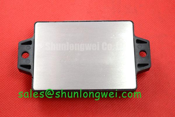
The Mitsubishi PM15CKF120 is a highly integrated power module that consolidates a three-phase converter, a three-phase inverter, and a brake chopper circuit into a single, compact package. This Converter-Inverter-Brake (CIB) configuration provides a streamlined solution for controlling low-power AC motors and other switching applications. By integrating these essential power stages, the module significantly reduces system complexity, component count, and assembly time for power system engineers.
- Core Specifications: 1200V | 15A | CIB Configuration
- Key Advantages: Simplifies power stage design, reduces PCB footprint.
- Primary Function: Provides a complete front-end and inverter solution for motor drives.
For detailed electrical and thermal characteristics, please refer to the official PM15CKF120 Datasheet.

Technical Analysis for System Integration
The primary value of the PM15CKF120 lies in its functional integration. By housing the AC-to-DC converter, DC-to-AC inverter, and dynamic brake circuit in one module, it eliminates the need for multiple discrete component selections and complex interconnects. This architecture is particularly beneficial for space-constrained applications, where reducing the size of the power electronics is a critical design goal. The module’s structure simplifies thermal management by consolidating the main heat-generating components onto a single isolated baseplate.
A crucial parameter for any power module is its thermal resistance, Rth(j-c). This value can be compared to the width of a pipe; a lower thermal resistance signifies a wider pipe, allowing heat to flow more easily from the active silicon to the heatsink. The PM15CKF120 is specified with distinct thermal resistance values for its inverter IGBTs, freewheeling diodes, brake chopper, and converter diodes. This level of detail enables engineers to perform accurate thermal simulations, ensuring the junction temperatures remain within safe operating limits under various load conditions. For further reading, consult resources on IGBT thermal design.
Optimized Application Scenarios
The characteristics of the PM15CKF120 make it suitable for a range of low-power industrial applications.
- Small AC Motor Drives: The all-in-one CIB design provides the complete power stage needed for variable frequency drives (VFDs) up to approximately 2.2 kW, minimizing design effort.
- Servo Amplifiers: In motion control systems, its compact footprint and integrated brake chopper are ideal for developing precise and responsive servo drives.
- General-Purpose Inverters: For applications requiring a simple and reliable AC output, this module offers a robust and field-tested solution.
- Auxiliary Power Supplies: The module can be adapted for use in various switched-mode power supply topologies where a three-phase input is available.
This module is an optimal match for low-power industrial motion control systems requiring a compact power stage with simplified assembly and proven reliability.
Key Specifications of the PM15CKF120
| Absolute Maximum Ratings (Tj = 25°C unless otherwise specified) | ||
|---|---|---|
| Parameter | Symbol | Rating |
| Collector-Emitter Voltage (Inverter) | VCES | 1200V |
| Collector Current (Inverter) | IC | 15A |
| Collector Power Dissipation (Inverter) | PC | 92W |
| Repetitive Peak Reverse Voltage (Converter) | VRRM | 1600V |
| Isolation Voltage | Viso | 2500 Vrms |
Engineer’s FAQ
What is the main advantage of using a CIB module like the PM15CKF120 over discrete components?
The primary benefit is system simplification. A CIB module integrates the three-phase input rectifier, the IGBT inverter, and the brake chopper into a single component. This reduces PCB design complexity, lowers the component count, minimizes stray inductance, and shortens assembly time compared to a solution built from individual diodes and IGBTs.
What are the key considerations for heatsink mounting?
For proper thermal management, the module’s baseplate must make uniform contact with the heatsink. Use a thermally conductive grease with a recommended thickness as specified in the datasheet. Mounting screws should be tightened evenly to the recommended torque (typically 1.47 ~ 1.96 N·m for M5 screws) to prevent warping the baseplate and ensure low contact thermal resistance.
Does this module include gate drive or protection circuits?
The PM15CKF120 is a power integrated module (PIM) and does not include the integrated gate drive and protection circuits found in an Intelligent Power Module (IPM). The system designer is responsible for implementing the external gate driver circuit, as well as protection features such as over-current, short-circuit, over-temperature, and under-voltage lockout.
What is the function of the integrated brake chopper?
The brake chopper is used for dynamic braking in motor drive applications. When the motor decelerates, it acts as a generator, sending regenerative energy back to the DC bus and increasing its voltage. The brake chopper circuit, connected to an external braking resistor, activates to dissipate this excess energy as heat, preventing the DC bus voltage from rising to a dangerous level.
Design Enablement
By integrating the three core power functions of a low-power drive into a single, thermally efficient package, the PM15CKF120 provides a robust foundation for industrial control systems. This approach allows engineering teams to focus on higher-level control logic and system features, accelerating the development cycle for compact and reliable motor control solutions.