Technical Guide to the FF300R12KE3G: Infineon’s 1200V 300A Dual IGBT Module
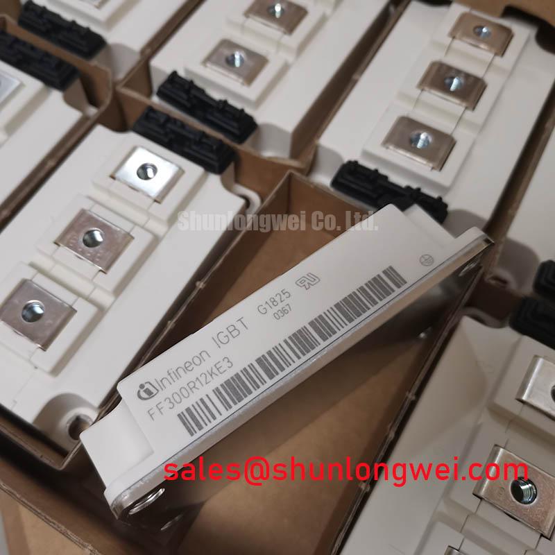
FF300R12KE3G Infineon 1200V 300A Dual IGBT Module
Overview & Unique Engineering Value
The FF300R12KE3G is an industry-standard 62mm half-bridge dual IGBT Module rated at 1200V and 300A. Developed by Infineon, it utilizes Trenchstop™ IGBT3 technology alongside highly efficient EmCon freewheeling diodes. This specific combination addresses the critical design trade-off between switching speed and low conduction losses in medium-power converters.
By achieving a low collector-emitter saturation voltage ($V_{CE(sat)}$ of 1.7V typical at $125^circtext{C}$), this module reduces overall thermal load. This drop in heat generation simplifies cooling system requirements and cuts gate driver design complexity. Engineers can reference our FF300R12KE3 technical review for comprehensive circuit integration guidelines.


Technical Deep-Dive: Trenchstop™ IGBT3 and EmCon Diode Synergy
The architectural foundation of the FF300R12KE3G relies on Infineon TRENCHSTOP™ IGBT3 silicon. Traditional planar gate structures suffer from higher vertical resistance. In contrast, the trench gate design features vertical channels that minimize cell pitch and carrier concentration profiles. This structural shift is part of the ongoing trench gate evolution. It yields a steep drop in on-state saturation voltage, significantly increasing overall electrical efficiency.
Think of the thermal resistance ($R_{thJC}$) of this module as the diameter of a drainage pipe. Just as a wider pipe allows water to drain rapidly to avoid flooding, a low thermal resistance of 0.075 K/W allows heat to flow quickly away from the silicon junctions to the external heatsink. This efficient heat transfer prevents localized thermal hotspots. It also preserves the structural integrity of the internal silicone gel insulation under high-current operations.
The integrated EmCon HE freewheeling diode features a soft-recovery waveform under high $di/dt$ conditions. This soft-recovery capability reduces electromagnetic interference (EMI) and mitigates turn-on overvoltage spikes. By matching the switching characteristics of the IGBT and diode, engineers can optimize turn-off transitions. This optimization prevents parasitic turn-on events without requiring oversized snubber components.
Target System Architectures & Applications
- Industrial Motor Drives (VFDs): Symmetrical half-bridge configuration makes this module an excellent fit for three-phase AC inverter stages operating at 2–10 kHz.
- Solar Inverters: Low conduction losses maximize power harvesting efficiency in utility-scale central inverters.
- Uninterruptible Power Supplies (UPS): Symmetrical turn-on and turn-off times ensure low total harmonic distortion (THD) under variable loads.
The FF300R12KE3G is a reliable choice for standard industrial converters requiring high power density and thermal robustness in a 62mm package.
FF300R12KE3G Key Technical Specifications
| Parameter Category | Specification Description | Value (Typical / Max) |
|---|---|---|
| Absolute Maximum Ratings | Collector-Emitter Voltage ($V_{CES}$) | 1200 V |
| Continuous DC Collector Current ($I_{C}$) | 300 A ($T_C = 80^circtext{C}$) | |
| Repetitive Peak Collector Current ($I_{CRM}$) | 600 A | |
| IGBT Electrical Characteristics | Collector-Emitter Saturation Voltage ($V_{CE(sat)}$) | 1.70 V (typ, $T_{vj} = 125^circtext{C}$) |
| Gate Threshold Voltage ($V_{GE(th)}$) | 5.0 V (min) – 6.5 V (max) | |
| Input Capacitance ($C_{ies}$) | 21.0 nF | |
| Thermal & Mechanical Properties | Thermal Resistance, Junction to Case ($R_{thJC}$) | 0.075 K/W (per IGBT) |
| Isolation Test Voltage ($V_{ISOL}$) | 2.5 kV (AC, 1 minute) |
Engineer FAQ
How do I mitigate switching transients when using the FF300R12KE3G in high-inductance DC buses?
Switching transients should be controlled by optimizing gate resistance ($R_G$) values and using a low-inductance busbar design. Excessive busbar stray inductance causes high overvoltage turn-off spikes. Engineers should read about parasitic inductance impact to understand how to design layout symmetries that minimize these voltage overshoots.
What is the recommended gate voltage range for reliable switching of this module?
The module requires a standard gate drive voltage of $+15text{V}$ for turn-on. To prevent parasitic turn-on from Miller capacitance under high $dv/dt$ conditions, we recommend a negative bias voltage of $-8text{V}$ to $-15text{V}$ for turn-off.
How does this module perform under short-circuit conditions?
The FF300R12KE3G features short-circuit ruggedness. It is rated to withstand a short-circuit duration ($t_{sc}$) of up to $10,mutext{s}$ at $T_{vj} = 125^circtext{C}$ and $V_{GE} = 15text{V}$. This window allows gate driver protection circuits to detect desaturation and execute a safe, soft shutdown.
Design Integrity & Sourcing
Incorporating the FF300R12KE3G into converter designs provides predictable power loss calculations and proven mechanical compatibility. The standard 62mm module housing allows drops-in upgrades to legacy platforms. By utilizing standard packaging with verified Trenchstop™ IGBT3 characteristics, engineers can achieve consistent thermal and electrical performance across production runs.