Toshiba MG75J6ES50 3-Phase IGBT Module (600V, 75A): Technical Overview and Applications
Toshiba MG75J6ES50 Silicon N-Channel IGBT Module (600V, 75A)
Introduction and Core Technical Highlights
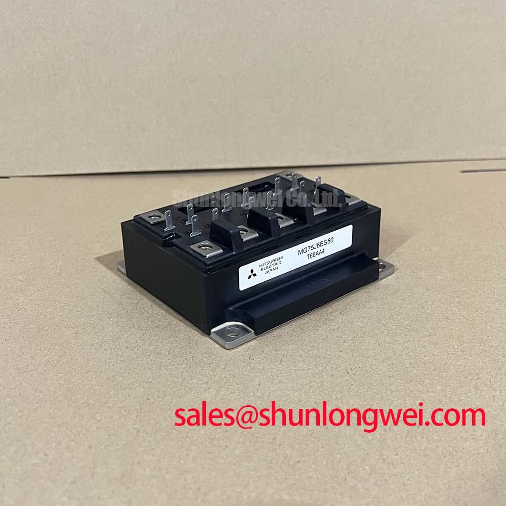
The Toshiba MG75J6ES50 is a silicon N-channel insulated gate bipolar transistor module configured in a compact 3-phase six-pack bridge inverter configuration. This module integrates high-speed switching characteristics with low conduction losses, delivering a highly efficient solution for medium-power power semiconductors applications. Designers often ask how to simplify 3-phase gate drive layouts while maintaining overall thermal performance. The integrated six-pack architecture of the MG75J6ES50 reduces external terminal connections, helping layout designers minimize parasitics.
- Core Ratings: 600V VCES | 75A IC | 2.7V Max VCE(sat)
- Engineering Advantages: Lower overall conduction power loss and simplified gate drive physical layout.
Download Official Toshiba MG75J6ES50 Datasheet (PDF)


Technical Performance Analysis
The performance of the MG75J6ES50 is anchored by its balance of conduction and switching parameters. Conduction efficiency is primarily determined by the collector-emitter saturation voltage (VCE(sat)), which typically sits at 2.1 V under IC = 75A and VGE = 15V. Minimizing this saturation voltage reduces on-state power losses, which is critical in maintaining high efficiency during continuous operational cycles.
For transient switching, the turn-on time (ton) of 0.8 microseconds and turn-off time (toff) of 1.5 microseconds ensure clean transition states. However, fast switching transitions make the circuit vulnerable to voltage overshoot caused by stray inductance. To counter this, engineers must pay close attention to gate drive impedance and the selection of turn-off gate resistors. By prioritizing thermal management, the module’s copper baseplate provides an isolated thermal pathway, ensuring reliable heat conduction to the main heatsink.
To visualize this thermal dynamic, think of the channel’s thermal resistance (Rth(j-c)) as a highway lane system. A high resistance represents a narrow, single-lane road that causes traffic (heat) to build up, raising the chip’s junction temperature. The low junction-to-case thermal resistance of the MG75J6ES50 behaves like a wide multi-lane highway, enabling thermal energy to escape quickly. This fast thermal dissipation keeps the junction temperature safely below its 150°C absolute maximum limit.
Integrating high-quality silicone gel insulation within the housing further protects the internal dies from environmental humidity and thermal cycling fatigue. The physical design is typical of a high-performance IGBT Module, providing isolated housing designed to withstand harsh operating environments over long lifecycles.


Optimized Application Scenarios
- Variable Frequency Drives (VFDs): The integrated three-phase bridge simplifies layout design in AC Variable Frequency Drive (VFD) motors up to 600V ratings.
- Industrial Servo Controllers: Low switching delays and precise current handling match the high-dynamic demands of positioning systems.
- Uninterruptible Power Supplies (UPS): Fast transition speeds support steady, high-efficiency switching under load-sharing conditions.
- Welding Power Supplies: The robust RBSOA capability provides reliability under heavy inductive spikes typical of high-current welding processes.
Best Match: The MG75J6ES50 is optimized for three-phase motor control and industrial power conversion systems operating under 600V bus voltages.
Key Specifications Parameter Table
| Category | Parameter | Symbol | Value | Unit |
|---|---|---|---|---|
| Absolute Maximums | Collector-Emitter Voltage | VCES | 600 | V |
| Gate-Emitter Voltage | VGES | ±20 | V | |
| Collector Current (DC) | IC | 75 | A | |
| Collector Power Dissipation (Tc=25°C) | P_C | 350 | W | |
| Electrical Characteristics | Collector-Emitter Saturation Voltage | VCE(sat) | 2.1 (typ) / 2.7 (max) | V |
| Diode Forward Voltage | VF | 2.5 (max) | V | |
| Turn-off Time | toff | 1.5 (max) | µs | |
| Thermal Ratings | Thermal Resistance (IGBT) | Rth(j-c) | 0.35 | °C/W |
| Thermal Resistance (Diode) | Rth(j-c) | 0.70 | °C/W |
Engineer FAQ
Q1: What are the gate drive recommendations to prevent parasitic turn-on in the MG75J6ES50?
Selecting an appropriate gate resistor (RG) is critical to balance switching losses and EMI. Utilizing a negative off-bias voltage (typically -5V to -15V) helps prevent parasitic turn-on caused by high dv/dt transients, bypassing the gate through the internal Miller capacitance. You can learn more about this by studying techniques on mastering the Miller plateau.
Q2: How does the internal diode performance impact the recovery behavior of this module?
The built-in Fast Recovery Diodes (FRDs) provide a low forward voltage (VF) of 2.5V and rapid reverse recovery times, which minimizes freewheeling recovery losses and limits high-frequency noise spikes during inductive load transitions.
Q3: Can the MG75J6ES50 be paralleled for higher power output?
Yes, but care must be taken to match external gate path impedances and trace lengths. Minor differences in parameter distribution may cause current imbalances. Standard practices for power semiconductors should be implemented during physical layout and thermal interface routing.
Summary Perspective
By offering a highly integrated three-phase N-channel architecture within a single package, this module enables engineers to optimize layout footprint without sacrificing conduction efficiency or switching speed. It remains a reliable standard block for robust medium-voltage industrial power conversion designs.