An In-Depth Guide to the Infineon FZ2400R12HP4 1200V 2400A High-Power IGBT Module
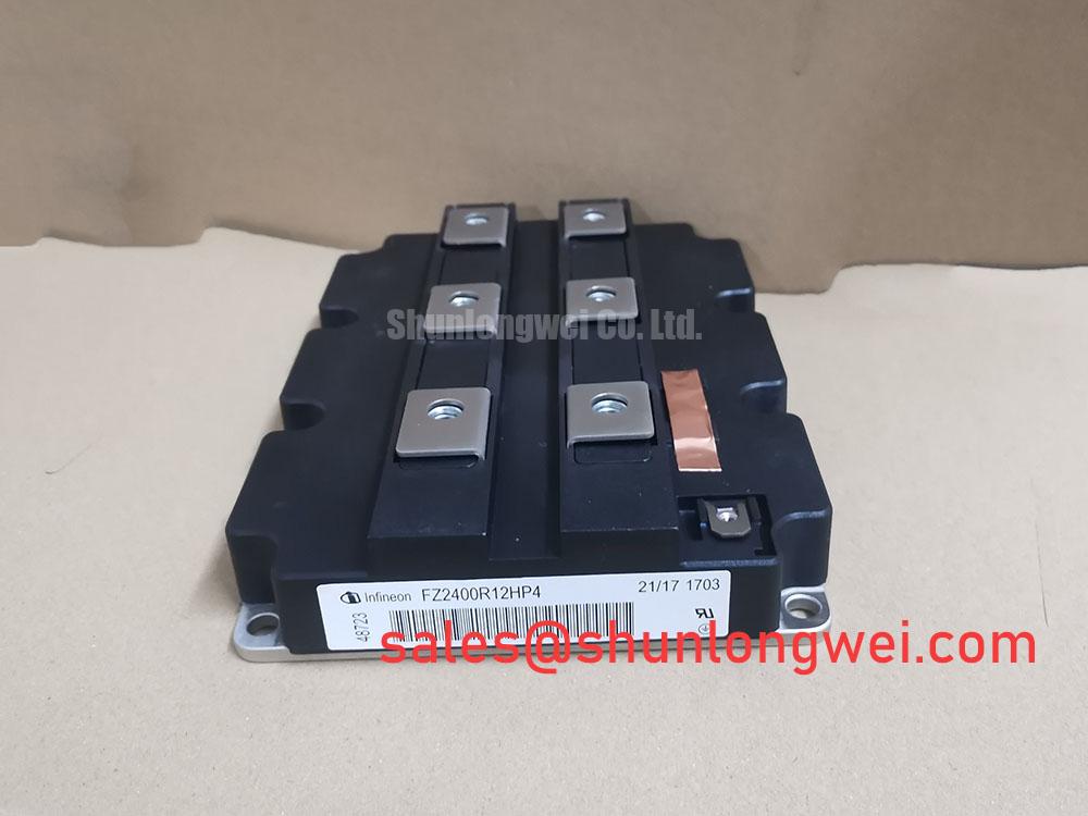
Infineon FZ2400R12HP4 High-Power 1200V 2400A IGBT Module
Introduction and Core Technical Parameters
The Infineon FZ2400R12HP4 is an industry-standard, high-power single-switch IGBT Module engineered specifically for high-capacity power conversion systems. Utilizing advanced Infineon TRENCHSTOP™ IGBT4 technology, this device delivers a highly optimized balance between conduction and switching losses, making it ideal for megawatt-range applications. For system designers asking how to manage extreme currents without complex paralleling architectures, this unified single-switch module offers a straightforward and highly reliable solution.
- Collector-Emitter Voltage (VCES): 1200V (at Tvj = 25°C)
- Continuous DC Collector Current (IC nom): 2400A (at TC = 100°C)
- Typical Saturation Voltage (VCE(sat)): 1.70V (at IC = 2400A, Tvj = 125°C)
- Package Design: Highly robust IHM-B package with isolated baseplates
Engineering benefits of this module include a significant reduction in overall thermal management overhead and a highly predictable switching behavior under dynamic loads, which simplifies gate driver design.
Download Official Infineon FZ2400R12HP4 Datasheet (PDF)


Technical Analysis and Engineering Design Value
The structural foundation of the FZ2400R12HP4 lies in its trench gate field-stop architecture. This design significantly reduces the collector-emitter saturation voltage (VCE(sat)) compared to older non-punch-through (NPT) designs. A lower saturation voltage translates directly to reduced conduction losses during the on-state. By minimizing these losses, the module operates cooler, improving system-level efficiency and reducing the thermal burden on your heatsink assembly.
To understand the thermal advantage, consider a simple thermal pipe analogy. You can visualize the module’s thermal resistance (Rthjc) as the physical width of a water drainpipe. A wider pipe allows water to flow out rapidly without backing up. Similarly, the exceptionally low junction-to-case thermal resistance (typically 0.015 K/W for the IGBT) acts as a wide thermal pipe, allowing heat to escape quickly to the heatsink. This keeps the internal silicon junction well below its maximum operating temperature limit of Tvj op = 150°C.
The module also incorporates a fast freewheeling diode with soft recovery characteristics. This is a crucial feature that dampens voltage overshoots during fast turn-off transitions. Turn-off transitions are a common source of electromagnetic interference (EMI) and electrical overstress. Combined with a robust short-circuit withstand time (tsc ≥ 10 µs at 800V), the FZ2400R12HP4 provides the ruggedness necessary for industrial environments prone to supply fluctuations and transient load faults.



Applications and Suitability
- High-Power Inverters: The continuous 2400A rating allows for direct integration into multi-megawatt wind turbine converters and centralized utility-scale solar arrays.
- Industrial Motor Drives: Provides seamless torque and speed control in large-scale pumps, fans, and compressors when used in a Variable Frequency Drive (VFD).
- Grid-Tie Power Systems: Ideal for Flexible AC Transmission Systems (FACTS), Static Var Compensators (SVC), and high-voltage DC (HVDC) power distribution interfaces.
- Uninterruptible Power Supplies (UPS): Supports high-density battery energy storage backup systems where rapid, highly reliable switching is mandatory.
Best-Fit Recommendation: The FZ2400R12HP4 is optimized for systems requiring robust 1200V block capabilities with single-phase currents up to 2400A under rigorous continuous operation.
Key Specifications Parameter Table
| Category | Parameter Symbol | Test Conditions / Value |
|---|---|---|
| Maximum Rated Values | VCES (Collector-Emitter Voltage) | 1200 V (at Tvj = 25°C) |
| IC nom (Nominal DC Current) | 2400 A (at TC = 100°C) | |
| ICRM (Repetitive Peak Current) | 4800 A (for tp = 1 ms) | |
| Electrical Characteristics | VCE(sat) (Saturation Voltage) | 1.70 V (typ, at IC = 2400A, Tvj = 125°C) |
| VGE(th) (Gate Threshold Voltage) | 5.1 V to 6.5 V (at IC = 91.0 mA) | |
| QG (Total Gate Charge) | 19.0 µC (at VGE = -15V to +15V) | |
| Thermal Characteristics | RthJC (Junction-to-Case IGBT) | 0.015 K/W (max, per IGBT module element) |
| Tvj op (Operating Junction Temp) | -40°C to 150°C |
Engineer FAQ
Q1: What are the primary failure mechanisms to guard against under high thermal stress?
A1: Solder fatigue and bond wire lift-off are the primary long-term wear-out mechanisms. You can read our detailed root cause analysis of IGBT failures to understand how to design protection loops and mitigate these thermal cycling stresses.
Q2: Why is the Kelvin Emitter connection critical for the FZ2400R12HP4?
A2: The module operates at currents up to 2400A. At this scale, even nanohenry-level stray inductances in the power path cause substantial voltage drops during switching (V = L * di/dt). The auxiliary Kelvin Emitter bypasses this voltage drop in the gate-drive circuit, ensuring accurate gate-source control signals and preventing false triggering.
Q3: How does the silicone gel insulation protect this high-power package?
A3: High-voltage modules require robust insulation to prevent partial discharge and catastrophic tracking breakdown. The internal silicone gel encapsulates the power chips and substrate. For a detailed breakdown of this protection mechanism, explore our guide on silicone gel and module insulation reliability.
Summary
The Infineon FZ2400R12HP4 stands as a premier solution for heavy-duty power conversion. By combining high current density with low VCE(sat) conduction profiles and robust thermal dissipation limits, it allows power electronics engineers to construct compact, reliable, and highly efficient megawatt-scale power architectures.