Fuji Electric 7D100D-050EHR 7-in-1 Darlington Module: Features, Specs, and Applications
Fuji Electric 7D100D-050EHR 7-in-1 Darlington Module
Introduction and Core Highlights
The Fuji Electric 7D100D-050EHR is a highly integrated 7-in-1 power Darlington transistor module. It is engineered to simplify power stage architecture in low-to-medium frequency inverter drives. This module features a 500V, 100A rating, consolidating a converter, inverter, and brake chopper circuit into a single physical block. For developers working with 200V-230V AC input systems, it offers a complete, space-saving topology.
- Core Specifications: 500V | 100A | 7-in-1 Integration
- Design Advantages: Drastic reduction in PCB space and simplified thermal interface layout.
- Stray Reduction: Co-packaged layout minimizes internal stray parasitic inductances.
Download Official Datasheet (PDF)
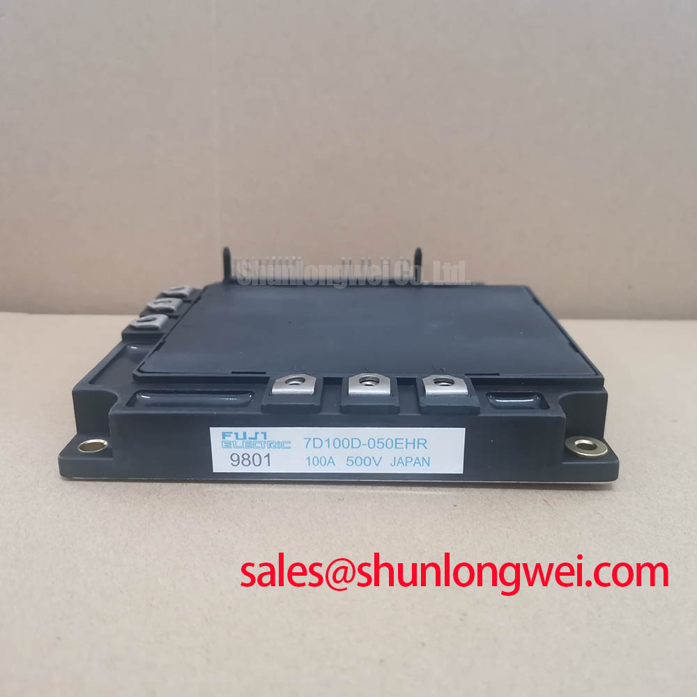

Technical Analysis of the Darlington Configuration
The Darlington transistor configuration inside the 7D100D-050EHR provides exceptional DC current gain. This high gain allows low control currents to drive high output loads, simplifying base drive design. Think of this arrangement like a mechanical lever; a small input force at one end lifts a heavy weight at the other. This configuration exhibits a stable saturation voltage of around 2.0V under full load conditions.


Integrating the rectifier, inverter, and brake stages onto a single substrate shortens internal circuit tracks. This compact layout mitigates parasitic inductance, preventing destructive voltage overshoot during switching transitions. Furthermore, the co-packaged antiparallel diodes act as freewheeling paths. You can read more about how these components handle current in our guide to the diode’s role in system performance.
For thermal management, the module utilizes an isolated copper baseplate. The junction-to-case thermal resistance is restricted to 0.21 °C/W per transistor. You can visualize thermal resistance as a bottleneck in a water pipe. A smaller resistance acts like a wider pipe, allowing heat to escape faster to the heatsink. Designers can calculate dynamic temperature responses using the transient thermal impedance curve to prevent thermal fatigue.

Optimized Application Scenarios
- Variable Frequency Drives (VFDs): Compact AC motor speed controllers benefit from the pre-integrated rectifier and inverter stages.
- AC Servo Controllers: Systems requiring high dynamic torque response leverage the module’s high current gain structure.
- Uninterruptible Power Supplies (UPS): High-reliability inverter stages utilize the integrated freewheeling diodes for reactive power paths.
- Legacy Drive Upgrades: Ideal for upgrading or replacing legacy blocks such as the older 7D30D-050EHR to achieve higher current handling capabilities.
The 7D100D-050EHR is optimized for 200V industrial AC motor control applications requiring integrated rectifier and inverter stages within one compact module.
Key Specifications Parameter Table
| Absolute Maximum Ratings (Inverter Part) | ||
|---|---|---|
| Collector-Emitter Voltage ($V_{CES}$) | 500 V | Maximum continuous blocking voltage |
| Collector Current ($I_C$) | 100 A | Continuous DC collector current |
| Collector Current (Pulse, $I_{CP}$) | 200 A | Peak pulse current capability |
| Collector Power Dissipation ($P_C$) | 600 W | Per transistor at case temperature of 25°C |
| Converter Part (Rectifier Bridge) | ||
| Repetitive Peak Reverse Voltage ($V_{RRM}$) | 800 V | Peak reverse blocking voltage |
| Average Output Current ($I_O$) | 100 A | 50/60Hz sine wave, three-phase full wave rectified |
| Thermal and Package Characteristics | ||
| Junction-to-Case Resistance ($R_{th(j-c)}$) | 0.21 °C/W | For inverter transistor element |
| Case-to-Heatsink Resistance ($R_{th(c-f)}$) | 0.05 °C/W | With thermal paste applied correctly |
| Isolation Voltage ($V_{isol}$) | 2000 V AC | For 1 minute between terminals and baseplate |
Engineer FAQ
What is the maximum AC line input voltage for the 7D100D-050EHR?
The inverter portion of the module is rated for a maximum Collector-Emitter voltage of 500V. Therefore, it is designed for 3-phase AC input voltages up to 200V-230V AC. It should not be used on 380V/400V AC utility grids because the DC link voltage will exceed the module’s breakdown limit.
How do you calculate the thermal resistance of this module to the heatsink?
The total thermal resistance is calculated by adding the junction-to-case resistance of 0.21 °C/W to the case-to-heatsink contact resistance of 0.05 °C/W. Ensure the heatsink interface is flat and thermal grease is applied evenly to minimize contact resistance.
Does this module contain built-in gate drive circuitry?
No. The 7D100D-050EHR contains only the power semiconductors. An external base driver circuit is required to supply the necessary base current to turn on the Darlington pairs.
Conclusion
This integrated 7-in-1 power Darlington module provides a compact, robust platform for low-voltage industrial drives. By consolidating three power stages onto a single isolated copper baseplate, the 7D100D-050EHR enables engineers to minimize thermal bottlenecks, reduce design footprint, and simplify wiring layout. For comprehensive integration guidelines and test procedures, refer to the power semiconductors application note directory.