Mitsubishi CM600HU-24F: A Technical Analysis for High-Power Applications
Mitsubishi CM600HU-24F IGBT Module: 1200V 600A High Power
Introduction and Core Highlights
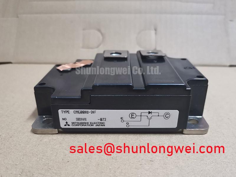
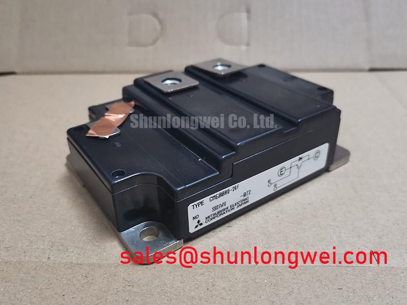
The Mitsubishi CM600HU-24F is a high-power, single IGBT module engineered for robust performance in demanding industrial power conversion systems. This module’s defining value is its combination of high current handling and excellent thermal efficiency, providing a reliable foundation for high-stress applications. Effective system design hinges on leveraging its low thermal impedance, which dictates heatsink requirements for maintaining operational stability under maximum load.
- Core Specifications: 1200V | 600A | VCE(sat) 2.2V (typ)
- Key Engineering Advantages: Facilitates high power density designs; simplified thermal management due to low thermal resistance.
Download the Official CM600HU-24F Datasheet (PDF)
Technical Analysis for System Integration
The CM600HU-24F is built around two central performance pillars: high current capacity and efficient heat dissipation. The 600A continuous collector current rating allows the module to manage substantial power throughput, making it suitable for driving large industrial motors and high-capacity power supplies without operating at the edge of its specifications. This high current headroom is critical for ensuring reliability and longevity in systems that experience frequent load variations or momentary current surges.
A key parameter for thermal design is the junction-to-case thermal resistance (Rth(j-c)), specified at a low 0.035°C/W for the IGBT. This value can be thought of as the width of a pipe for heat to escape the semiconductor chip. The CM600HU-24F’s low thermal resistance signifies a very wide pipe, enabling rapid and effective transfer of waste heat to the heatsink. This efficiency minimizes the junction temperature rise, which is crucial for preventing performance degradation and extending the module’s power cycling capability.
Furthermore, the collector-emitter saturation voltage (VCE(sat)) of 2.2V (typical) at the nominal 600A current is a direct indicator of conduction efficiency. Lower VCE(sat) translates into reduced power loss (P = VCE(sat) × IC), meaning less energy is wasted as heat during operation. This contributes to higher overall system efficiency and lessens the burden on the cooling system, potentially allowing for more compact heatsink designs.

Optimized Application Scenarios
The specifications of this module align it with several high-power industrial applications:
- General Purpose Inverters & VFDs: The 1200V and 600A ratings are ideal for three-phase Variable Frequency Drives (VFDs) operating on 480V to 690V AC lines, providing ample margin and current handling for precise motor control.
- Servo Controls: Its capability to handle high currents makes it well-suited for large servo drives that require rapid acceleration and deceleration of heavy loads.
- Uninterruptible Power Supplies (UPS): The module’s robust nature ensures reliable power delivery in high-capacity UPS systems, capable of handling the full load transfer without compromise.
- Welding Equipment: It can effectively manage the high-current, pulsed-power demands characteristic of industrial welding power supplies.
This module is a strong candidate for systems needing robust 600A switching at 1200V, where reliable thermal performance is a primary design requirement.
Key Specification Parameters
| Absolute Maximum Ratings | |
|---|---|
| Collector-Emitter Voltage (VCES) | 1200V |
| Collector Current (IC) @ Tc=80°C | 600A |
| Maximum Power Dissipation (PC) @ Tc=25°C | 3570W |
| Operating Junction Temperature (Tj) | -40 to +150°C |
| Electrical & Thermal Characteristics | |
| Collector-Emitter Saturation Voltage (VCE(sat)) (Typ, @ 600A) | 2.20V |
| Gate-Emitter Threshold Voltage (VGE(th)) | 5.5 ~ 7.5V |
| Collector Cut-off Current (ICES) @ VCE=VCES | 1mA |
| Thermal Resistance, Junction to Case (Rth(j-c)) IGBT | 0.035°C/W |
| Isolation Voltage (Visol) (AC, 1 min.) | 2500V |
Engineer’s FAQ
What is the primary factor for thermal design with the CM600HU-24F?
The most critical factor is ensuring a low-resistance thermal path from the module’s baseplate to the ambient environment. This involves selecting a heatsink with a thermal resistance significantly lower than the module’s Rth(j-c) of 0.035°C/W and using a quality thermal interface material. Proper mounting torque is essential to minimize contact thermal resistance.
What are the recommended gate drive voltage levels?
The datasheet specifies a gate-emitter voltage (VGE) of +15V for turn-on. For turn-off, a negative voltage of -5V to -10V is typically recommended to provide strong immunity against noise-induced parasitic turn-on, a common issue explored in guides to robust gate drive design.
Can these modules be connected in parallel?
Yes, but successful paralleling requires careful engineering. The circuit layout must be symmetrical to ensure balanced current sharing between modules. This includes matched gate drive impedances and minimized, identical parasitic inductances in the power connections. It is also advisable to thermally couple the modules to maintain similar operating temperatures.
Final Engineering Statement
The CM600HU-24F delivers a well-balanced combination of high-current switching and thermal stability in an industry-standard insulated package. Its specifications provide engineers with the necessary performance for creating efficient, high-power converters and motor drives where operational reliability under sustained heavy loads is a non-negotiable requirement.