Electric motors are devices that transform electrical energy into mechanical energy, which may be used to move articulated systems. The electric motor must be capable of producing substantial torque at low speeds and be extremely efficient across the load range. It also requires a straightforward control and driving mechanism. Although they require more complex control, brushless DC motors (BLDCs) are finding homes in robotic applications due to their better performance.
BLDC motors are gaining in popularity across the board thanks to their lower production costs. The arrival of consumer drones and e-bikes, in particular, have resulted in widespread adoption of BLDC motors, which were previously used in high-end industrial applications only.
Engineers who are developing these BLDC motor applications have changed over the last two decades, as much as motor control has. Today’s engineer prefers to concentrate on what makes their device design unique rather than constructing a complex propulsion system. Engineers are focusing on sleeker designs with a minimal form factor, intuitive user interfaces, real-time capabilities, functional safety, and data sharing in the cloud.
The control problem
A significant part of a robotic system is the motor controller. Several control strategies can be used to operate a robotic manipulator, or robotic arm. The technology utilized and how it is implemented can have a considerable impact on the manipulator’s performance and, as a result, on the range of viable applications. The mechanical design of the manipulator and the actuation system, on the other hand, influence the type of control scheme that may be used.
While the robot’s job is typically stated in an operational space, the control actions are implemented in the joint space in terms of the motion of the various parts of the robot. As a result, it is reasonable to examine two types of control schemes: one for joint space and another for operational space. The controller structure is a closed-loop control system in both schemes to leverage the benefits of feedback in terms of resilience to potential unknown effects on the model and minimization of disturbance effects such as noise.
The joint-space control issue entails solving the manipulator’s inverse kinematics to convert motion requirements from the operational to the joint space. The control scheme is then created so that the mechanical structure’s motion can follow the intended motion. In comparison, control in the operational space necessitates a far higher level of computational complexity in which the kinematic inversion is incorporated into the closed-loop system.
The operating system in use, as well as various approaches and circuits based on the motor and application needs, are required for controlling the speed and direction of the motors. The aim of a motor controller is to be able to operate an electric motor manually or automatically (start-stop, inversion, speed, torsion, and protection against voltage overloads).
Traditional motors have a number of benefits that BLDC motors do not. BLDC and AC-driven permanent magnet synchronous motors (PMSMs) can provide the required precision and high efficiency in a compact form factor. In addition, brush-type DC motors and AC induction motors are easy to connect and operate, unlike BLDCs and PMSMs, which are more complex.

The DRV8301-69M-KIT engine kit includes a Three-Phase driver with an integrated buck regulator and current-shunt amplifiers. Click for a larger image. (Source: Texas Instruments Inc.)
For example, BLDCs use techniques such as sensorless vector control (also called field-oriented control, or FOC) that offer good efficiency and the advantage of eliminating sensor hardware, thereby reducing cost and improving reliability. The problem for designers is that sensorless vector control is complicated to implement, so its use can lengthen development time, adding cost and possibly exceeding time-to-market forecasts.
To solve this dilemma, designers can turn to development platforms such as the DRV8301-69M-KIT engine kit from Texas Instruments Inc. that includes a DRV8301 three-phase gate driver integrated with a buck regulator and current-shunt amplifiers and an InstaSPIN-FOC and InstaSPIN-MOTION–enabled Piccolo TMS320F28069M microcontroller (MCU) board.
Despite the design complexity, the key benefits of a BLDC arise from its construction features. They typically offer a 15% to 20% higher efficiency than brushed solutions, need less maintenance due to their brushless design, and deliver a flat torque curve at all rated speeds. In many applications, brushed motors have been replaced by BLDCs due to recent advancements in Semiconductor technology, improvements in permanent magnets, and increased demand for higher efficiency.
DC drivers
BLDCs use electronic commutation, which allows for better current switching. It leads to greater torque, accurate speed control over a wide range, and improved motor performance. A half-bridge or half-H-bridge circuit is found in most BLDC motor controllers. This circuit design, unlike an H-bridge, has only two switches: one high-side and one low-side Transistor.
Single-phase, two-phase, and three-phase BLDC motors are available. The three-phase type is the most popular. The motor stator’s number of windings correlates to the number of phases, but the rotor poles might be any number of pairs, depending on the application.
A fundamental component of BLDC control is the driver. It is a voltage-output power amplifier that drives the half-bridge circuit’s high-current high-side and low-side IGBT gates.
One example is the Power Integrations 400-W BRD1167 and BRD1267 BridgeSwitch ICs that provide a continuous RMS phase current of 1.33 A and a FREDFET DC output current of 11.5 A. They are self-powered and come in the InSOP-24C surface-mount package, just like the rest of the BridgeSwitch family. These devices support all major MCU and motor-control methods and can operate single-phase or multi-phase high-voltage synchronous or asynchronous motors. Overcurrent, over-/undervoltage, and overtemperature protection are included in all BridgeSwitch ICs, simplifying IEC 60335 and IEC 60730 certification.
Another example is Monolithic Power Systems Inc.’s MP6612D reversible motor driver that uses an H-bridge. It can operate a DC motor, a stepper motor winding, and other loads. Four N-channel power mosfets and an internal charge pump create the gate driver voltages in the H-bridge. The DIR and ENBL pins are used to control the outputs.

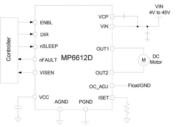
MP6612D block diagram (Source: Monolithic Power Systems Inc.)
Wide-bandgap semiconductors
Electric motor designs that extract higher performance from increasingly more compact platforms are required for emerging electronic applications. Motor driver circuits relying on classic silicon MOSFETs and IGBTs are struggling to fulfill the new criteria. It is becoming more difficult for designers to keep power losses under control as silicon technology approaches theoretical limits for power density, breakdown voltage, and switching frequency. The principal consequences of these constraints are reduced efficiency and additional performance issues at high operating temperatures and switching rates.
Wide-bandgap (WBG) semiconductors such as silicon carbide (SiC) and gallium nitride (GaN) devices are used in motor control because they provide faster switching that may be needed for motors operating at high fundamental frequencies and requiring well-filtered ripple. However, the high switching speeds achieved by WBG devices, while offering higher conversion efficiencies, also generate very fast voltage variations that result in high-voltage change rates (dV/dt) that can stress the insulation of the motor windings. Power-electronic applications, therefore, have two main objectives: managing thermal issues and reducing system size.
Manufacturers like Texas Instruments have developed GaN integrated power devices that help get the best performance from WBG devices. For example, the LMG5200 provides an 80-V GaN half-bridge power stage with enhancement-mode GaN FETs. The device consists of two GaN FETs powered by one high-frequency GaN FET driver in a half-bridge arrangement.
TI supplies the TIDA-00909, a reference design for high-frequency motor drives utilizing a three-phase inverter with three LMG5200s, to make designing with the device easier. For simple performance assessment, the TIDA-00909 comes with a suitable interface for connecting to a C2000 MCU LaunchPad development kit.

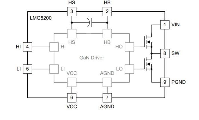
LMG5200 block diagram (Source: Texas Instruments Inc.)

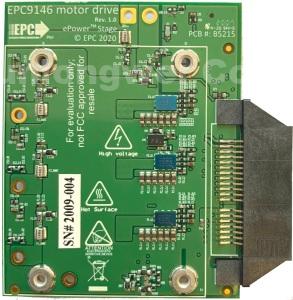
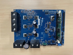
EPC9146 power board. Click for a larger image. (Source: EPC)
Another example is EPC’s EPC9146 power board, which incorporates the EPC2152 monolithic ePower Stage with an integrated gate driver using EPC’s proprietary GaN IC technology, and delivers an 80-V maximum device voltage and 15-A maximum output current. With a PWM frequency of up to 3 MHz, it can run at full load. The EPC9146 offers features for power-drive applications, such as a monolithic power stage with an integrated gate driver, regulated auxiliary power rails for housekeeping supplies, voltage and temperature sensing, precise current sensing, and protective functions.
The EPC9146 can be paired with EPC9147 series mating boards to allow the user to control the power board directly through a mainstream MCU board, leveraging existing resources for quick development purposes.
The complexity of a robot requires the right driver to perform its function properly related to the industrial application. WBG semiconductors are employed in motor control because they allow quicker switching, which is necessary for motors operating at high fundamental frequencies. Rather than creating a complicated propulsion system, engineers prefer to focus on what makes their gadget design distinctive.
about Efficient Power Conversion (EPC)Monolithic Power SystemsPower IntegrationsTexas Instruments